
Multi F Engineering Manual

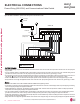
Creating a Balanced / Quality Piping System
Unlike designing duct-work or chilled and hot water pipe systems where balancing dampers, ball valves, orifices, circuit setters, or other
flow control devices can be installed to modify or balance the flow of cooling medium, these cannot be used in a Multi F system. Therefore,
variable refrigerant flow systems have to be designed to be “self balanced.” Balanced liquid refrigerant distribution is solely dependent on
the designer using the correct pipe size for each segment. Pipe sizing considerations include pipe length, pipe segment pressure drop
relative to other pipe segments in the system, type and quantity of elbows, bends present, fitting installation orientation, and end use device
elevation differences.
$Q\¿HOGFKDQJHVVXFKDVUHURXWLQJVKRUWHQLQJRUOHQJWKHQLQJDSLSHVHJPHQWDGGLQJRUHOLPLQDWLQJHOERZVDQGRU¿WWLQJVUHVL]LQJDGGLQJ
RUHOLPLQDWLQJLQGRRUXQLWVFKDQJLQJWKHPRXQWLQJKHLJKWRUPRYLQJWKHORFDWLRQRIDGHYLFHRU¿WWLQJGXULQJLQVWDOODWLRQPXVWEHGRQHZLWKFDX
WLRQDQG$/:$<69(5,),('LQ/$7608/7,)62)7:$5(EHIRUHVXSSOLHVDUHSXUFKDVHGRULQVWDOOHG'RLQJVRHQVXUHVSUR¿WDEOHLQVWDOODWLRQ
HOLPLQDWHVUHZRUNDQGHQVXUHVHDVLHUV\VWHPFRPPLVVLRQLQJ
The designer must avoid creating excessive pressure drop. When liquid refrigerant is subjected to excessive pressure drop, liquid re
IULJHUDQWZLOOFKDQJHVWDWHDQG³ÀDVK´WRYDSRU9DSRUSUHVHQWLQDVWUHDPRIOLTXLGUHIULJHUDQWEHIRUHUHDFKLQJWKHLQGRRUXQLWFRLORUEUDQFK
GLVWULEXWLRQXQLWIRU0XOWL)0$;V\VWHPVUHVXOWVLQDORVVRIV\VWHPFRQWURODQGFDXVHVGDPDJHWRWKHFRPSRQHQWV
The pipe system must
be designed in a manner that avoids the creation of unwanted vapor.
Refrigerant Piping System Verification
To ensure that the refrigerant piping design is suitable for the system, a LATS refrigerant piping design software report must be provided with
every Multi F order. Following the installation, if any changes or variations to the design were necessary, an “as-built” LATS piping design
software report must be provided to LG prior to system commissioning. User must always check the LATS report actual pipe layout versus
pipe limits.
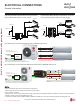
REFRIGERANT PIPING DESIGN
Manual Layout Procedure
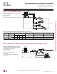
1. Choose the location of the indoor units on the building drawing.
2. Choose the location of all Y-branch and branch distribution units (if a Multi F MAX system) and note them on the building drawing. Verify
that all fittings are positioned per the guideline limitations in “LG Engineered Multi F MAX Y-Branch Kit”
3. Plan the route for interconnecting piping. Draw a one-line depiction of the pipe route chosen on the building drawing.
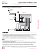
4. Calculate the actual length of each pipe segment and note it on the building drawing.
5. Using the data obtained while selecting the system components, list the corrected cooling capacity next to each indoor unit on the drawing.
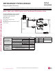
6. Starting at the indoor unit located farthest from the outdoor unit, sum the corrected cooling capacity of all indoor units served by the pipe
segment for each branch and runout pipe (indoor units and branch distribution units [Multi F MAX systems only]). Record these values
next to each segment.
7. Verify the size of the liquid and vapor lines.
8. If a Multi F MAX system, refer to the branch distribution unit information and the Y-branch kit information to verify the part number of each
Y-branch and branch distribution unit based on the connected downstream nominal capacity served.
9. Calculate the equivalent pipe length in feet of each pipe segment. If a Multi F MAX system, Y-branch equivalent lengths must be totaled
with the upstream segment only. Use equivalent pipe length data when it is provided with field-purchased fittings. If not available, use the
data provided to estimate the equivalent length of field-provided pipe and fittings for each segment. Equivalent lengths must be totaled
with the upstream segment only.
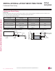
10. Verify the equivalent pipe length complies with product limitations. If the limitations are exceeded, either reroute the pipe or change the
location of the indoor unit, Y-branch fittings and branch distribution units (if Multi F MAX systems), so the design conforms with all limita-
tions.
11. If pipe length is adjusted as described in Step 10 above, verify again if the length of the design complies with the product limitations.
12. 8VH/$760XOWL)VRIWZDUHWRYHULI\WKHPDQXDOO\VL]HGSLSHGHVLJQLVDFFHSWDEOH:KHQHQWHULQJWKHOHQJWKRISLSHVHJPHQWVLQ/$76
Multi F software, enter the equivalent pipe length. Account for the additional pressure drop created by elbows, valves, and other fittings
present in each segment by adding their respective equivalent pipe length to the actual pipe length.
Creating a Balanced System / Manual Layout Procedure
'XHWRRXUSROLF\RIFRQWLQXRXVSURGXFWLQQRYDWLRQVRPHVSHFL¿FDWLRQVPD\FKDQJHZLWKRXWQRWL¿FDWLRQ
©/*(OHFWURQLFV86$,QF(QJOHZRRG&OLIIV1-$OOULJKWVUHVHUYHG³/*´LVDUHJLVWHUHGWUDGHPDUNRI/*&RUS
DESIGN & PRACTICES | 203
Refrigerant Piping Design and Best Practices
MULTI
F
MAX
MULTI
F