
Multi F Engineering Manual

STD. WALL-MOUNTED | 65
Standard Wall-Mounted
'XHWRRXUSROLF\RIFRQWLQXRXVSURGXFWLQQRYDWLRQVRPHVSHFL¿FDWLRQVPD\FKDQJHZLWKRXWQRWL¿FDWLRQ
©/*(OHFWURQLFV86$,QF(QJOHZRRG&OLIIV1-$OOULJKWVUHVHUYHG³/*´LVDUHJLVWHUHGWUDGHPDUNRI/*&RUS
MULTI
F
MAX
MULTI
F
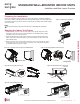
Factory Supplied Parts
Factory Supplied Materials
• Owner’s Manual
• Installation Manual
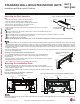
• Level
• Screwdriver
• Electric drill
• Hole core drill
• Flaring tool set
• Spanner (Half union)
• Thermometer
Factory Supplied Parts and Materials
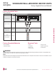
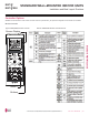
7DEOH Parts Table.
Required Tools
STANDARD WALL-MOUNTED INDOOR UNITS
Part Quantity Image
Installation Plate One (1)
Type “A” Screws Five (5)
Type “B” Screws
(M4 x 12L)
Two (2)
:LUHOHVV
Controller with Holder
AKB74955602
One (1)
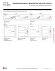
7,000 ~ 15,000 Btu/h Indoor Units
18,000 and 24,000 Btu/h Indoor Units
WARNING
,QVWDOODWLRQZRUNPXVWEHSHUIRUPHGE\WUDLQHGSHUVRQQHODQGLQDFFRUGDQFHZLWKQDWLRQDOZLULQJVWDQGDUGVDQGDOOORFDORURWKHUDSSOLFDEOHFRGHV
,PSURSHULQVWDOODWLRQFDQUHVXOWLQ¿UHHOHFWULFVKRFNSK\VLFDOLQMXU\RUGHDWK
Note:
Read all instructions before installing this product. Become familiar with the unit’s components and connections, and the order of installation. Incorrect
installation can degrade or prevent proper operation.