
Multi F Engineering Manual

'XHWRRXUSROLF\RIFRQWLQXRXVSURGXFWLQQRYDWLRQVRPHVSHFL¿FDWLRQVPD\FKDQJHZLWKRXWQRWL¿FDWLRQ
©/*(OHFWURQLFV86$,QF(QJOHZRRG&OLIIV1-$OOULJKWVUHVHUYHG³/*´LVDUHJLVWHUHGWUDGHPDUNRI/*&RUS
68 | STD. WALL-MOUNTED
Multi F and Multi F MAX Indoor Unit Engineering Manual
MULTI
F
MAX
MULTI
F
Installation and Best Layout Practices
Power Wiring / Communications Cable Guidelines
STANDARD WALL-MOUNTED INDOOR UNITS
• Follow manufacturer’s circuit diagrams in the technical manuals.
• Confirm power source specifications.
• Confirm that the electrical capacity is sufficient.
• Starting current must be maintained ±10 percent of the rated current marked on the outdoor unit name plate.
• Confirm cable thickness specifications.
• It is required that a circuit breaker is installed, especially if conditions could become wet or moist.
• Include a disconnect in the power wiring system, add an air gap contact separation of at least 1/8 inch in each active (phase) conductor.
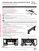
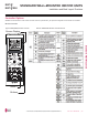
Terminal block
Power wiring /
communications cable
Wired Remote Controlle
r
Terminal (Optional)
Cable restraint
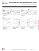
)LJXUH&RQQHFWLQJ3RZHU:LULQJ&RPPXQLFDWLRQV&DEOH
Connect Power Wiring and
Communications Cable
1. Insert the power wiring / communications cable from the outdoor
unit or branch distribution unit (Multi F MAX systems only) through
the bottom of the indoor unit.
2. Connect each wire to its appropriate terminal on the indoor unit
control board. Verify that the color and terminal numbers from the
outdoor unit or branch distribution unit (Multi F MAX systems only)
wiring match the color and terminal numbers on the indoor unit.
3. Secure power wiring/communications cable with cable restraint.
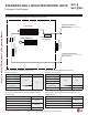
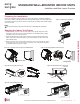
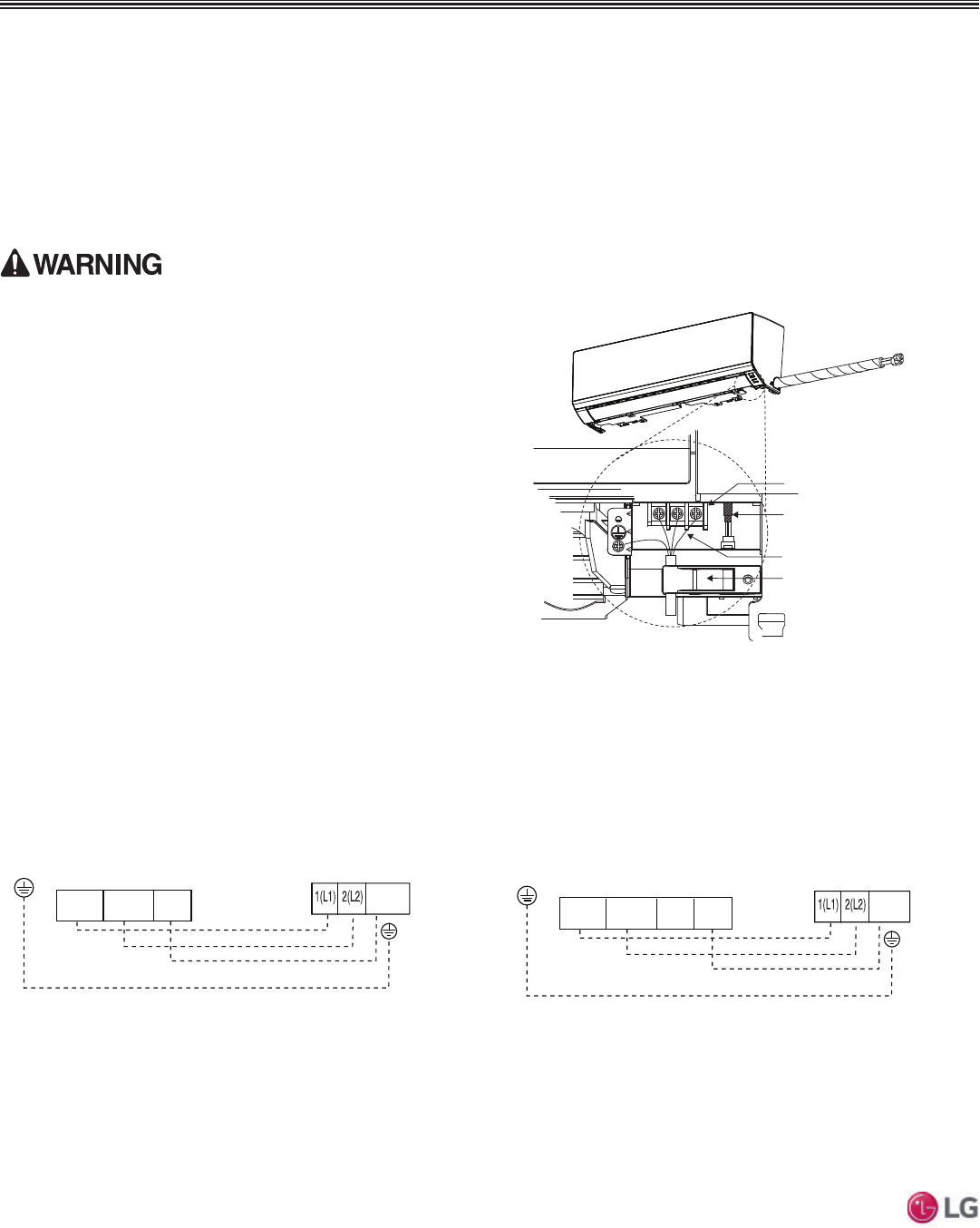
)LJXUH6LPSOL¿HG9LHZRI,QGRRU8QLWWR2XWGRRU8QLW%UDQFK
Distribution Unit Terminal Connections—LMN079HVT, LSN090HSV5,
LSN120HSV5 and LMN159HVT.
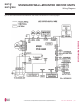
)LJXUH6LPSOL¿HG9LHZRI,QGRRU8QLWWR2XWGRRU8QLW%UDQFK
Distribution Unit Terminal Connections— LSN180HSV5 and
LMN249HVT.
Indoor Unit Terminal Block
GND
Outdoor Unit Terminal Block or
Branch Distribution Unit Terminal Block
(Multi F MAX Systems Only)
GND
GRN / YLW
BR
BL
RD
3 or S
32(L2)1(L1)
Indoor Unit Terminal Block
1(L1 ) 2(L2)
GND
Outdoor Unit Terminal Block or
Branch Distribution Unit Terminal Block
(Multi F MAX Systems Only)
GND
GRN / YLW
BR
BL
RD
3
3 or S
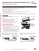
• Loose wiring will cause unit to malfunction, overheat, and catch
fire, resulting in severe injury or death.
Note:
• 7HUPLQDO VFUHZV ZLOO EHFRPH ORRVH GXULQJ WUDQVSRUW 3URSHUO\
tighten the terminal connections during installation.
A voltage drop will cause the following problems:
• 0DJQHWLF VZLWFK YLEUDWLRQ IXVH EUHDNV RU GLVWXUEDQFH WR WKH
normal function of an overload protection device.
• Compressor will not receive the proper starting current.