
Multi F Engineering Manual
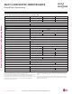
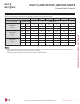
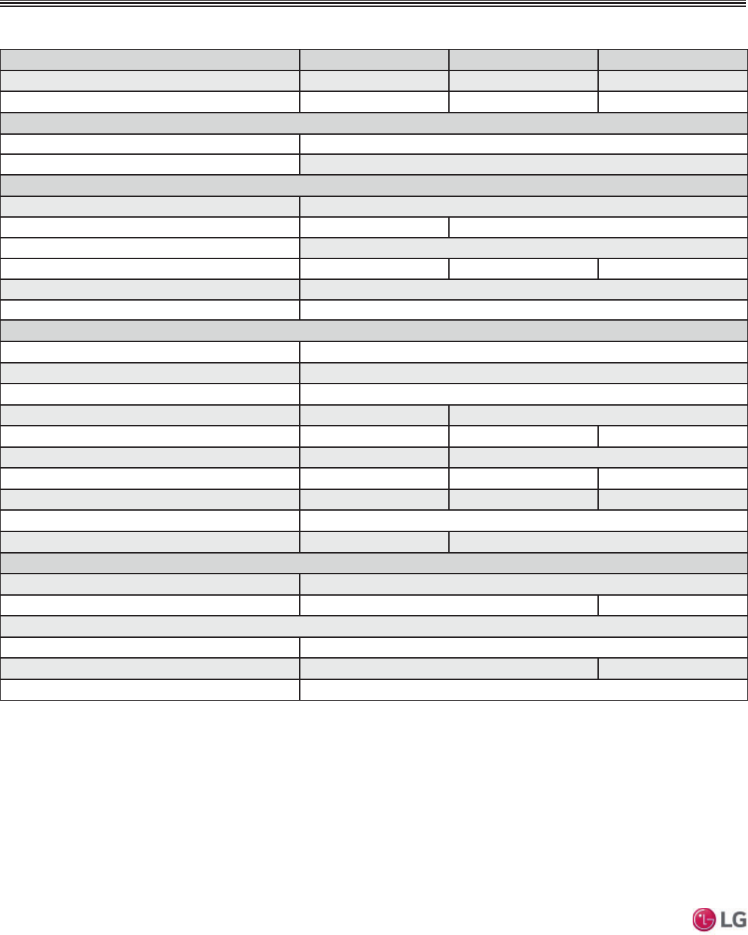
Model Name LDN097HV4 LDN127HV4 LDN187HV4
Nominal Cooling Capacity (Btu/h)
1
9,000 12,000 18,000
Nominal Heating Capacity (Btu/h)
1
10,400 13,800 20,800
Operating Range
&RROLQJ):%
57-77
Heating (°F DB)
59-81
Fan
Type
Sirocco
0RWRU2XWSXW:[4W\
19 x 1 5 x 1, 19 x 1
Motor/Drive
Brushless Digitally Controlled / Direct
Airflow Rate CFM (H/M/L)
318 / 247 / 194 353 / 300 / 247 530 / 441 / 353
Factory Set External Static Pressure (in. wg)
0.10
Max. External Static Pressure (in. wg)
0.20
Unit Data
Refrigerant Type
2
R410A
Refrigerant Control
EEV
Power Supply V, Ø, Hz
3
208-230, 1, 60
Rated Amps (A)
0.40 0.80
Sound Pressure Level dB(A) (H/M/L)
4
30 / 26 / 23 31 / 28 / 27 36 / 34 / 31
'LPHQVLRQV:[+['LQ
27-9/16 x 7-15/32 x 27-9/16 35-7/16 x 7-15/32 x 27-9/16
1HW8QLW:HLJKWOEV
39 51 48.5
6KLSSLQJ:HLJKWOEV
46 60 57.3
3RZHU:LULQJ&RPPXQLFDWLRQV&DEOH1R[$:*
5
4 x 18
Heat Exchanger (Row x Column x Fin / inch) x Number
(2 x 11 x 14) x 1 (2 x 11 x 18) x 1
3LSH6L]H
Liquid Line (in.)
1/4
Vapor Line (in.)
3/8 1/2
Connection Size
Liquid Line (in.)
1/4
Vapor Line (in.)
3/8 1/2
Drain O.D. / I.D. (in.)
1-1/4, 1
1
Nominal capacity is rated 0 ft. above sea level with corresponding refrigerant piping length in
accordance with standard length of each outdoor unit and a 0 ft. level difference between outdoor and
indoor units. All capacities are net with a combination ratio between 95 – 105%.
Nominal cooling capacity rating obtained with air entering the indoor unit at 80ºF dry bulb (DB) and 67ºF
ZHWEXOE:%DQGRXWGRRUDPELHQWFRQGLWLRQVRI)GU\EXOE'%DQG)ZHWEXOE:%
Nominal heating capacity rating obtained with air entering the indoor unit at 70ºF dry bulb (DB) and 60ºF
ZHWEXOE:%DQGRXWGRRUDPELHQWFRQGLWLRQVRI)GU\EXOE'%DQG)ZHWEXOE:%
2
This unit comes with a dry helium charge.
3
$FFHSWDEOHRSHUDWLQJYROWDJH99
4
Sound pressure levels are tested in an anechoic chamber under ISO Standard 3745 and are the
same in both cooling and heating mode. These values can increase due to ambient conditions during
operation.
5
$OOSRZHUZLULQJFRPPXQLFDWLRQVFDEOHWRWKH,'8VEHPLQLPXP$:*FRQGXFWRUVWUDQGHG
shielded or unshielded (if shielded, must be grounded to chassis at ODU only) and must comply with
applicable local and national codes.
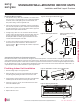
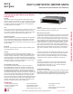
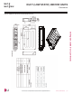
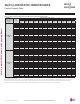
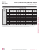
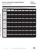
DUCT (LOW STATIC) INDOOR UNITS
*HQHUDO'DWD6SHFL¿FDWLRQV
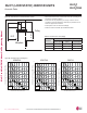
7DEOH Multi F Ceiling-Concealed Low-Static Ducted Indoor Unit General Data.
'XHWRRXUSROLF\RIFRQWLQXRXVSURGXFWLQQRYDWLRQVRPHVSHFL¿FDWLRQVPD\FKDQJHZLWKRXWQRWL¿FDWLRQ
©/*(OHFWURQLFV86$,QF(QJOHZRRG&OLIIV1-$OOULJKWVUHVHUYHG³/*´LVDUHJLVWHUHGWUDGHPDUNRI/*&RUS
74 | DUCT (LOW STATIC)
Multi F and Multi F MAX Indoor Unit Engineering Manual
MULTI
F
MAX
MULTI
F