ENGLISH FRANÇAIS ESPAÑOL INSTALLATION MANUAL AIR CONDITIONER Please read this installation manual completely before installing the product. Installation work must be performed in accordance with the national wiring standards by authorized personnel only. Please retain this installation manual for future reference after reading it thoroughly. Standard Inverter MFL68061228 Rev.00_060218 http://www.lghvac.com www.lg.com Copyright © 2017 - 2018 LG Electronics Inc. All Rights Reserved.
TIPS FOR SAVING ENERGY ENGLISH TIPS FOR SAVING ENERGY Here are some tips that will help you minimize the power consumption when you use the air conditioner. You can use your air conditioner more efficiently by referring to the instructions below: • Do not cool excessively indoors. This may be harmful for your health and may consume more electricity. • Block sunlight with blinds or curtains while you are operating the air conditioner.
IMPORTANT SAFETY INSTRUCTIONS 3 READ ALL INSTRUCTIONS BEFORE USING THE APPLIANCE. Always comply with the following precautions to avoid dangerous situations and ensure peak performance of your product ! WARNING It can result in serious injury or death when the directions are ignored ! CAUTION It can result in minor injury or product damage when the directions are ignored ! WARNING • Installation or repairs made by unqualified persons can result in hazards to you and others.
IMPORTANT SAFETY INSTRUCTIONS ENGLISH Operation • Do not share the outlet with other appliances. - It will cause an electric shock or a fire due to heat generation. • Do not use the damaged power cord. - Otherwise, it may cause a fire or electrical shock. • Do not modify or extend the power cord randomly. - Otherwise, it may cause a fire or electrical shock. • Take care so that the power cord may not be pulled during operation. - Otherwise, it may cause a fire or electrical shock.
IMPORTANT SAFETY INSTRUCTIONS • Install the drain hose to ensure that drain can be securely done. - Otherwise, it may cause water leakage. • Install the product so that the noise or hot wind from the outdoor unit may not cause any damage to the neighbors. - Otherwise, it may cause dispute with the neighbors. • Always inspect gas leakage after the installation and repair of product. - Otherwise, it may cause the failure of product. • Keep level parallel in installing the product.
TABLE OF CONTENTS ENGLISH TABLE OF CONTENTS 2 TIPS FOR SAVING ENERGY 3 IMPORTANT SAFETY INSTRUCTIONS 7 INSTALLATION OF OUTDOOR UNIT 7 Installation Places 7 Piping length and the elevation 8 WIRING CONNECTION 8 Electrical Wiring 8 Connecting Cables between Indoor Unit and Outdoor Unit 10 Connecting the cable to Outdoor Unit 11 CONNECTING COPPER PIPES 11 Preparation of Piping 12 Plumbing materials and storage methods 13 Connecting the pipes to the Outdoor unit 14 Forming the pipi
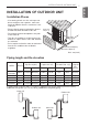
INSTALLATION OF OUTDOOR UNIT 7 ENGLISH INSTALLATION OF OUTDOOR UNIT Installation Places - If an awning is built over the unit to prevent direct sunlight or rain exposure, make sure that heat radiation from the condenser is not restricted. - Ensure that the spaces indicated by arrows around front, back and side of the unit. - Do not place animals and plants in the path of the warm air. - Take the air conditioner weight into account and select a place where noise and vibration are minimum.
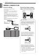
WIRING CONNECTION ENGLISH WIRING CONNECTION Electrical Wiring - All wiring must comply with local requirements. - Select a power source that is capable of supplying the current required by the air conditioner. - Use a recognized ELCB(Electric Leakage Circuit Breaker) between the power source and the unit. A disconnection device to adequately disconnect all supply lines must be fitted. - Model of circuit breaker recommended by authorized personnel only.
WIRING CONNECTION Use round pressure terminals for connections to the power terminal block. When laying ground wiring, you must use round pressure terminals. Round pressure terminal Power wire (Ground wire) When none are available, follow the instructions below. - Do not connect wiring of different thicknesses to the power terminal block. (Slack in the power wiring may cause abnormal heat.) - When connecting wiring which is the same thickness, do as shown in the figure below.
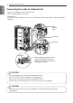
WIRING CONNECTION ENGLISH Connecting the cable to Outdoor Unit - Remove the side panel for wiring connection. - Use the cord clamp to fix the cord. - Earthing work Connect the cable of diameter more to the earthing terminal provided in the control box and do earthing. Main Terminal Block Cord clamp Cord clamp Insulation When connecting main power cable, make sure the rubber bushes are properly used in knock-out holes after removing the Insulation.
CONNECTING COPPER PIPES 11 ENGLISH CONNECTING COPPER PIPES Preparation of Piping Flaring work Main cause of gas leakage is defect in flaring work. Carry out correct flaring work in the following procedure. - Firmly hold copper tube in a bar(or die) as indicated dimension in the table above. - Carry out flaring work using dedicated flaring tool for R-410A as shown below. Cut the pipes and the cable. - Use the accessory piping kit or the pipes purchased locally.
CONNECTING COPPER PIPES NOTE Always blow nitrogen into pipe which is brazed. Always use a non-oxidizing brazing material for brazing the parts and do not use flux. If not, oxidized film can cause clogging or damage to the compressor unit and flux can harm the copper piping or refrigerant oil.
CONNECTING COPPER PIPES 13 - Align the center of the piping and sufficiently tighten the flare nut by hand. - Finally, tighten the flare nut with torque wrench until the wrench clicks. When tightening the flare nut with torque wrench, ensure the direction for tightening follows the arrow on the wrench. Outside diameter Torque mm inch N·m kgf·m Ø6.35 1/4 14~18 1.4~1.8 Ø9.52 3/8 34~42 3.5~4.3 Ø12.7 1/2 49~61 5.0~6.2 Ø15.88 5/8 69~82 7.0~8.4 Ø19.05 3/4 100~120 10.0~12.
CONNECTING COPPER PIPES ENGLISH Forming the piping Form the piping by wrapping the connecting portion of the indoor unit with insulation material and secure it with two kinds of vinyl tape. - If you want to connect an additional drain hose, the end of the drain outlet should be routed above the ground. Secure the drain hose appropriately. In cases where the outdoor unit is installed below the indoor unit perform the following. 1 Tape the piping, drain hose and connecting cable from down to up.
LEAKAGE TEST AND EVACUATION 15 ENGLISH LEAKAGE TEST AND EVACUATION Air and moisture remaining in the refrigerant system have undesirable effects as indicated below. 1 Pressure in the system rises. 2 Operating current rises. 3 Cooling(or heating) efficiency drops. 4 Moisture in the refrigerant circuit may freeze and block capillary tubing. 5 Water may lead to corrosion of parts in the refrigeration system.
LEAKAGE TEST AND EVACUATION ENGLISH Evacuation 1 Connect the charge hose end described in the preceding steps to the vacuum pump to evacuate the tubing and indoor unit. Confirm the "Lo and Hi" knob of the manifold valve is open. Then, run the vacuum pump. The operation time for evacuation varies with tubing length and capacity of the pump. The following table shows the time required for evacuation.
TEST RUNNING 17 Precautions in test running - The initial power supply must provide at least 90% of the rated voltage. Otherwise, the air conditioner should not be operated. ! NOTE • For test run, carry out the cooling operation firstly even during heating season. If heating operation is carried out firstly, it leads to the trouble of compressor. Then attention must be paid. • Carry out the test run more than 5 minutes without fail.
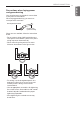
FUNCTION ENGLISH FUNCTION Pump Down Setting Procedure 1 Set the Dip Switch as follow after shutting the power source down. 1 LUU188HV LUU189HV LUU248HV 2 3 4 5 6 7 8 9 10 LUU368HV LUU428HV LUU488HV 2 Reset the power. 3 Red LED and Green LED of PCB lights during work. (The indoor unit is operated by force.) 4 If operation is done, Red LED will be turned off. If operation is not done normally, Red LED will blink.
SELF-DIAGNOSIS FUNCTION 19 ENGLISH SELF-DIAGNOSIS FUNCTION Error Indicator (Outdoor) Outdoor Error Ex) Error 21 (DC Peack) 2 Times 2 Times 2 Times LED01G (RED) 1s 1s 1s 1 Time 1 Time 1 Time LED02G (GREEN) 2s 2s LUU188HV LUU189HV LUU248HV Error Code Description LED 1 (Red) LUU368HV LUU428HV LUU488HV LED 2 (Green) Indoor status 21 DC Peak(IPM Fault) 2times ◑ 1time ◑ OFF 22 Max. CT(CT2) 2times ◑ 2times ◑ OFF 23 DC Link Low Volt.
SELF-DIAGNOSIS FUNCTION ENGLISH Dip S/W Setting If you set the Dip Switch when power is on, the change in setting is not applicable. The changing setting is enabled only when Power is reset.
INSTALLATION GUIDE AT THE SEASIDE 21 ! NOTE • Air conditioners should not be installed in areas where corrosive gases, such as acid or alkaline gas, are produced. • Do not install the product where it could be exposed to sea wind (salty wind) directly. It can result corrosion on the product. Corrosion, particularly on the condenser and evaporator fins, could cause product malfunction or inefficient performance.
ENGLISH
US CANADA Please call the installing contractor of your product, as warranty service will be provided by them.