
Owner's Manual

10
Instructions for the installer
2.3.3 Connection to liquid gas
Use a standards-compliant pressure regulator and carry out the
connection to the gas cylinder in accordance with the regulations in
force.
Make sure that the supply pressure complies with the values
indicated in the paragraph “3.2/3.3 Burner and nozzle
characteristics table”.
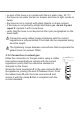
Screw the small hose connector F onto the
large hose connector A; connect the block
that this makes to the gas connector B (or
use the hose connector G which must be
connected directly to the gas connector B)
and place the seal C in between them. Push
the end of the rubber hose D on to the hose
connector A+F (or G) and to the outlet
connection of the pressure reducer on the
gas cylinder. Secure the end of the hose D to the hose connector
A+F (or G) with the standards-compliant clamp E.
The hose connector G illustrated is not supplied with the
appliance. Only use standards-compliant hose connectors.
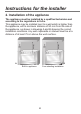
2.3.4 Connection with flexible steel hose (for all types of gas)
This type of connection can be made on both built-in
and free-standing appliances. Only use standards-
compliant steel hoses whose length is not greater than
2 metres. Screw the end of the flexible hose L, with the
seal C positioned between the B threaded
1
/2” external
gas connector (ISO 228-1).
At the end of the installation, check for any leaks
with a soapy solution, never with a flame.
For the connection between the cooker and the gas cylinder
use a portion of standards-compliant hose not less than 1.4 m
in length.