
Installation Guide


APPENDIX
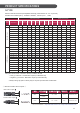
Fig.1 Mounting Type Fig.2 Clamping Type
①
②
①
②
①
②
①
②
A
B
B
A
① : 200mm(7.9 in)
② : 300mm(11.8 in)
Front : 6000Pa(125psf)
Rear : 5400Pa(113psf)
A : 200mm(7.9 in)
B : 400mm(15.7 in)
Front : 6000Pa(125psf)
Rear : 5400Pa(113psf)
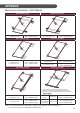
Fig.3 Clamping Type Fig.4 Clamping Type
A
B
B
A
A
B
A
B
A : 200mm(7.9 in)
B : 400mm(15.7 in)
Front : 6000Pa(125psf)
Rear : 5400Pa(113psf)
A : 120mm(4.7 in)
Front : 1800Pa(37.5psf)
Rear : 1800Pa(37.5psf)
B : 200mm(7.9 in)
Front : 2850Pa(60psf)
Rear : 2850Pa(60psf)
Fig.5 Clamping Type Fig.6 Clamping Type
A
B
B
A
C
C
B
A
①
②
①
②
①
①
* 4 point installation is allowed in the following cases:
1. Slope roof: If module is installed parallel to the rooftop.
dniw sa hcus dnats lanoitidda na htiw dellatsni fI :foor talF .2
A : 200mm(5.9 in)
B : 400mm(15.7 in)
Front : 6000Pa(125psf)
Rear : 5400Pa(113psf)
mm021 : A
(4.7 in)
*4point(①)
Front : 1800Pa(37.5psf)
Rear : 1800Pa(37.5psf)
C : 120mm(4.7in)
Front : 3200Pa(67psf)
Rear : 1800Pa(37.5psf)
A : 120mm
mm001± 528 : B
(32.5±3.9 in)
6point(①+②)
Front : 6000Pa(125psf)
Rear : 5400Pa(113psf)
Mechanical Installation : 60Cell Model
13
Note) All mechanical installation method(Fig.1 to Fig.6) in this appendix were not tested by UL.
(UL 1703, ULC 1703) It is evaluated by LG internal test.