ENGLISH FRANÇAIS ESPAÑOL INSTALLATION MANUAL AIR CONDITIONER Please read this installation manual completely before installing the product. Installation work must be performed in accordance with the national wiring standards by authorized personnel only. Please retain this installation manual for future reference after reading it thoroughly. 4-WAY CEILING CASSETTE MFL61971250 Rev.00_060818 www.lghvac.com www.lg.com Copyright © 2018 LG Electronics Inc. All Rights Reserved.
TIPS FOR SAVING ENERGY ENGLISH TIPS FOR SAVING ENERGY Here are some tips that will help you minimize the power consumption when you use the air conditioner. You can use your air conditioner more efficiently by referring to the instructions below: • Do not cool excessively indoors. This may be harmful for your health and may consume more electricity. • Block sunlight with blinds or curtains while you are operating the air conditioner.
IMPORTANT SAFETY INSTRUCTIONS READ ALL INSTRUCTIONS BEFORE USING THE APPLIANCE. Always comply with the following precautions to avoid dangerous situations and ensure peak performance of your product ! WARNING It can result in serious injury or death when the directions are ignored ! CAUTION It can result in minor injury or product damage when the directions are ignored ! WARNING • Installation or repairs made by unqualified persons can result in hazards to you and others.
IMPORTANT SAFETY INSTRUCTIONS ENGLISH Operation • Do not share the outlet with other appliances. - It will cause an electric shock or a fire due to heat generation. • Do not use the damaged power cord. - Otherwise, it may cause a fire or electrical shock. • Do not modify or extend the power cord randomly. - Otherwise, it may cause a fire or electrical shock. • Take care so that the power cord may not be pulled during operation. - Otherwise, it may cause a fire or electrical shock.
IMPORTANT SAFETY INSTRUCTIONS 5 • Install the drain hose to ensure that drain can be securely done. - Otherwise, it may cause water leakage. • Install the product so that the noise or hot wind from the outdoor unit may not cause any damage to the neighbors. - Otherwise, it may cause dispute with the neighbors. • Always inspect gas leakage after the installation and repair of product. - Otherwise, it may cause the failure of product. • Keep level parallel in installing the product.
TABLE OF CONTENTS ENGLISH TABLE OF CONTENTS 7 INSTALLATION PLACES 8 THE INDOOR UNIT INSTALLATION 9 Indoor Unit Drain Piping 10 Wiring Connection 12 Flaring work 13 Connection of piping 14 INSTALLATION OF DECORATIVE PANEL(ACCESSORY) 16 TEST RUNNING 17 INSTALLATION INSTRUCTIONS 17 Installer Setting - How to enter installer setting mode 18 Installer Setting - Installer Setting Code Table 19 Installer Setting - Setting Address of Central Control 19 Installer Setting - Checking Address of
INSTALLATION PLACES ENGLISH INSTALLATION PLACES 300(11-13/16) or more - There should not be any heat source or steam near the unit. - There should not be any obstacles to prevent the air circulation. - A place where air circulation in the room will be good. - A place where drainage can be easily obtained. - A place where noise prevention is taken into consideration. - Do not install the unit near the door way. - Ensure the spaces indicated by arrows from the wall, ceiling, or other obstacles.
THE INDOOR UNIT INSTALLATION Ceiling Level gauge Ceiling board Included Paper Cardboard on the bottom of packaging ! CAUTION TM/TN/TP Chassis 875(34-7/16) (Ceiling opening) • This air-conditioner uses a drain pump. • Install the unit horizontally using a level gauge. • During the installation, care should be taken not to damage electric wires. 787(30-15/16) (Hanging bolt)bolt) Unit size Unit size 840(33-1/16) 671(26-7/16) 840(33-1/16) ! NOTE Avoid the following installation location.
THE INDOOR UNIT INSTALLATION Wall Indoor Hanging bolt (W3/8 or M10) Nut (W3/8 or M10) Flat washer with insulation attached (Install insulation to be in contact with the indoor unit hanger part.) Spring washer (M10) Flat washer for M10 (accessory) Nut (W3/8 or M10) The following parts is option.
THE INDOOR UNIT INSTALLATION 1,000(39.4)~ 1,500(59.1) 800(31-1/2) or less ENGLISH 300(11.8) or less Drain raising pipe Drain hose(attached) Clamp metal(attached) Unit:mm(inch) Heat insulation material: Polyethylene foam with thickness more than 8mm(0.3inch). Drain test The air conditioner uses a drain pump to drain water. Use the following procedure to test the drain pump operation: - Connect the main drain pipe to the exterior and leave it provisionally until the test comes to an end.
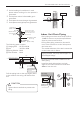
THE INDOOR UNIT INSTALLATION 11 Lock nut Conduit mounting plate Conduit Use round pressure terminals for connections to the power terminal block. When laying ground wiring, you must use round pressure terminals. Round pressure terminal Power wire (Ground wire) ! CAUTION The connecting cable connected to the indoor and outdoor unit should be complied with the following specifications (This equipment shall be provided with a cord set complying with the national regulation).
THE INDOOR UNIT INSTALLATION ENGLISH Flaring work 4 Flaring work Main cause of gas leakage is defect in flaring work. Carry out correct flaring work in the following procedure. 1 Cut the pipes - Carry out flaring work using flaring tool as shown below. Pipe diameter Inch (mm) A Inch (mm) Ø1/4 (Ø6.35) 0.04~0.05 (1.1~1.3) - Use the accessory piping kit or the pipes purchased locally. - Measure the distance between the indoor and the outdoor unit.
THE INDOOR UNIT INSTALLATION 13 For Single zone Align the center of the piping and sufficiently tighten the flare nut by hand. IDU ODU Capacity (kBtu/h) Single Zone 18 Refrigerant Connections Pipe size Liquid Gas 3/8 (Ø9.52) 5/8 (Ø15.88) h Indoor Unit (18k) includes the sockets. (Ø 6.35 → Ø 9.52 x 1EA, Ø 12.7 → Ø 15.88 x 1EA, Ø 9.52 → Ø 12.7 x 1EA) Finally, tighten the flare nut with torque wrench until the wrench clicks.
INSTALLATION OF DECORATIVE PANEL(ACCESSORY) ENGLISH INSTALLATION OF DECORATIVE PANEL(ACCESSORY) The decorative panel has its installation direction. Before installing the decorative panel, always remove the paper template. 1 Remove the packing and take out air inlet grille from front panel. 4 Insert two screws on diagonal corners of panel. Do not tighten the bolts completely. (The fixing screws are included in the indoor unit box.) Check the alignment of panel with the ceiling.
Link INSTALLATION OF DECORATIVE PANEL(ACCESSORY) 15 vane control connectors of front panel to indoor unit PCB. The position marking on PCB is as: Display connector : CN-DISPLAY Vane control connector: CN-VANE 1,2 CN-VANE 1,2 11 Install the air inlet grille and Filter on the panel. CN-DISPLAY 8 Close the cover for control box. ! CAUTION Install certainly the decorative panel. Cool air leakage causes sweating. ⇨ Water drops fall.
TEST RUNNING ENGLISH TEST RUNNING PRECAUTIONS IN TEST RUN - The initial power supply must provide at least 90% of the rated voltage. Otherwise, the air conditioner should not be operated. Connection of power supply - Connect the power supply cord to the independent power supply. Circuit breaker is required. - Operate the unit for 15 minutes or more. ! CAUTION • For test run, carry out the cooling operation firstly even during heating season.
INSTALLATION INSTRUCTIONS 17 Installer Setting - How to enter installer setting mode ! CAUTION Installer setting mode is to set the detail function of the remote controller. If the installer setting mode is not set correctly, it can cause problems to the product, user injury or property damage. This must be set by an certificated installer, and any installation or change that is carried out by a non-certificated person should be responsible for the results. In this case, free service cannot be provided.
INSTALLATION INSTRUCTIONS ENGLISH Installer Setting - Installer Setting Code Table No.
INSTALLATION INSTRUCTIONS 19 1 With the MODE button pressed, press the RESET button. 2 By using the temperature setting button, set the indoor unit address. - Setting range : 00 ~ FF 3 After setting the address, press the ON/OFF button toward the indoor unit 1 time. 4 The indoor unit will display the set address to complete the address setting. - The address display time and method can differ by the indoor uint type. 5 Reset the remote controller to use the general operation mode.
ENGLISH
US CANADA Please call the installing contractor of your product, as warranty service will be provided by them.