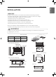
ENGLISH FRANÇAIS ESPAÑOL INSTALLATION MANUAL AIR CONDITIONER Please read this installation manual completely before installing the product. Installation work must be performed in accordance with the national wiring standards by authorized personnel only. Please retain this installation manual for future reference after reading it thoroughly. Ceilling Concealed Duct www.lghvac.com www.lg.com MFL67206507 Rev.05_052219 Copyright © 2013 - 2019 LG Electronics Inc. All Rights Reserved.
TIPS FOR SAVING ENERGY ENGLISH TIPS FOR SAVING ENERGY Here are some tips that will help you minimize the power consumption when you use the air conditioner. You can use your air conditioner more efficiently by referring to the instructions below: • Do not cool excessively indoors. This may be harmful for your health and may consume more electricity. • Block sunlight with blinds or curtains while you are operating the air conditioner.
IMPORTANT SAFETY INSTRUCTIONS 3 READ ALL INSTRUCTIONS BEFORE USING THE APPLIANCE. Always comply with the following precautions to avoid dangerous situations and ensure peak performance of your product ! WARNING It can result in serious injury or death when the directions are ignored ! CAUTION It can result in minor injury or product damage when the directions are ignored ! WARNING • Installation or repairs made by unqualified persons can result in hazards to you and others.
IMPORTANT SAFETY INSTRUCTIONS 4 ENGLISH • Make sure that a sekparate power supply circuit is provided for this unit and that all electrical work is carried out by qualified personnel according to local laws and regulations and this installation manual. An insufficient power supply capacity or improper electrical construction may lead to electric shocks or fire. • Be sure to switch off the unit before touching any electrical parts.
TABLE OF CONTENTS 2 3 6 7 TIPS FOR SAVING ENERGY 8 9 11 12 13 14 15 16 17 19 19 20 20 20 Ceiling dimension and hanging bolt location Indoor Unit Installation Air Filter Checking the Drainage Indoor Unit Drain Piping Combination indoor units Flaring work Connection of piping - Indoor, Outdoor, BD Unit Plumbing materials and storage methods Indoor Unit Drain Piping Drain test Heat insulation Wiring Connection Connection method of the connecting cable(Example) IMPORTANT SAFETY INSTRUCTIONS INSTALLATION PA
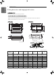
INSTALLATION PARTS ENGLISH INSTALLATION PARTS Air inlet vents Air outlet vents Air outlet vents Air filters Air intake vents Remote Controller (Accessory) Control box Air outlet vents Air filters Air intake vents Name Drain hose Clamp metal Washer for hanging bracket Clamp (Tie Wrap) Insulation for fitting Quantity 1 EA 2 EA 8 EA 4 EA 1 set Shape for gas pipe for liquid pipe * Screws for fixing panels are attached to decoration panel.
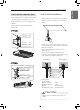
INSTALLATION ENGLISH INSTALLATION Indoor unit Install the air conditioner in the location that satisfies the following conditions. - The place shall easily bear a load exceeding four times the indoor unit’s weight. - The place shall be able to inspect the unit as the figure. - The place where the unit shall be leveled. - The place shall easily connect with the outdoor unit. - The place where the unit is not affected by an electrical noise. - The place where air circulation in the room will be good .
INSTALLATION 8 Installation of Unit Install the unit above the ceiling correctly. POSITION OF SUSPENSION BOLT - Apply a joint-canvas between the unit and duct to absorb unnecessary vibration. - Apply a filter Accessory at air return hole.
INSTALLATION - A place where the unit will be leveled and that can support the weight of the unit. - A place where the unit can withstand its vibration. - A place where service can be easily performed. Indoor Unit Installation - Select and mark the position for fixing bolts. - Drill the hole for set anchor on the face of ceiling.
INSTALLATION CAUTION 1 Install declination of the indoor unit is very important for the drain of the duct type air conditioner. 2 Minimum thickness of the insulation for the connecting pipe shall be 5 mm(3/16 inch). Front of view • The unit must be declined to the drain hose connected when finished installation.
INSTALLATION 11 ENGLISH Air Filter Air Filter Panel Rear Air outlet Low static duct type in case of suction from back side. Panel Rear Air outlet Air Filter Low static duct type in case of suction from bottom side. Cabinet case Panel Rear In case of suction from bottom size, bend the Panel rear and screw with cabinet case.
INSTALLATION ENGLISH Insulate the joint and tubes completely. INSULATION, OTHERS THERMAL INSULATION All thermal insulation must comply with local requirement.
INSTALLATION 13 CAUTION • Install declination of the indoor unit is very important for the drain of the duct type air conditioner. • Minimum thickness of the insulation for the connecting pipe shall be 19 mm(3/4 inch). Front of view The unit must be horizontal or declined to the drain hose connected when finished installation. Ceiling Drain test The air conditioner uses a drain pump to drain water.
INSTALLATION ENGLISH Combination indoor units (AMNW**G**A0 / TYPE B / TYPE D) BD unit (PMBD3641) The indoor units connectable to the outdoor unit are shown below Indoor Unit Type Vertical AHU Ceiling Concealed Duct (High Static) ! Outdoor Unit (Btu/h class) Capacity (Btu/h class) 36 k 54 k 24 k O O 36 k X O 24 k O O 36 k X O NOTE 1. The total capacity(in Btu/h unit) of connected indoor unit models represents the total sum of the figures expressed in the indoor model name. 2.
INSTALLATION 15 4 Flaring work Main cause of gas leakage is defect in flaring work. Carry out correct flaring work in the following procedure. 1 Cut the pipes - Carry out flaring work using flaring tool as shown below. Pipe diameter Inch (mm) A Inch (mm) Ø 1/4 (Ø 6.35) 0.04~0.05 (1.1~1.3) - Use the accessory piping kit or the pipes purchased locally. - Measure the distance between the indoor and the outdoor unit. - Cut the pipes a little longer than measured distance. - Cut the cable 1.5 m(4.
INSTALLATION ENGLISH Connection of piping - Indoor, Outdoor, BD Unit (AMNW**G**A0 / AMNW18GL2A1 / TYPE B / TYPE D) Align the center of the piping and sufficiently tighten the flare nut by hand. Capacity (kBtu/h) 24 36 ODU Single Zone Refrigerant Connections Pipe size Liquid Gas 1/4 (Ø 6.35) 1/2 (Ø 12.7) 3/8 (Ø 9.52) 5/8 (Ø 15.88) Refrigerant Connections Pipe size Liquid Gas 3/8 5/8 AMNW18GL2A1 (Ø 9.52) (Ø 15.
INSTALLATION 17 Pipe must be able to obtain the specified thickness and should be used with low impurities. Also when handling storage, pipe must be careful to prevent a fracture, deformity and wound. Should not be mixed with contaminations such as dust, moisture. Refrigerant piping on three principles Items Cause failure Drying Cleanliness Airtight Should be no moisture inside No dust inside.
INSTALLATION Welding, as when heating without nitrogen substitution a large amount of the oxide film is formed on the internal piping. The oxide film is a caused by clogging EEV, Capillary, oil hole of accumulator and suction hole of oil pump in compressor. It prevents normal operation of the compressor. In order to avoid this problem, Welding should be done after replacing air by nitrogen gas. When welding plumbing pipe, the work is required.
INSTALLATION 19 (TYPE B / C ) Upward routing not allowed Pipe clamp Indoor unit Maintenance drain port 1 Remove the Air Filter. - Drain piping must have down-slope (1/50 to 1/100): be sure not to provide up-and-down slope to prevent reversal flow. - During drain piping connection, be careful not to exert extra force on the drain port on the indoor unit. - The outside diameter of the drain connection on the indoor unit is 32 mm(1-1/4 inch).
INSTALLATION ENGLISH Heat insulation 1 (TYPE B / C / D) 1 1 Use the heat insulation material for the refrigerant piping which has an excellent heat-resistance (over 120 °C). 2 Precautions in high humidity circumstance: This air conditioner has been tested according to the "KS Standard Conditions with Mist" and confirmed that there is not any default.
INSTALLATION 21 - Open the control box cover and connect the remote controller cables, transmission cables and indoor power cables. - Control box cover is consist of two panel which are side and bottom panel. Side panel Bottom panel Control box cover can be separated from main body by 2 method. Case 1. Separate whole cover(when access from bottom of the product). Remove screws on the bottom panel and grab the both panel with two hands and pull down the whole cover. Case 2.
INSTALLATION ENGLISH After remove the control box cover, insert cables onto the bush and conduit and then connect at terminal block. Insulation, others Insulate the joint and tubes completely. THERMAL INSULATION All thermal insulation must comply with local requirement.
INSTALLATION 23 ENGLISH ! CAUTION The power connecting cable between the outdoor and indoor units must comply with the following specifications: NRTL Recognized (for example, UL or ETL recognized and CSA certified). AWG 18-4 is the minimum recommended wire size, however, the selected conductors must comply with local codes and be suitable for installation in wet locations.
REMOTE CONTROLLER INSTALLATION ENGLISH REMOTE CONTROLLER INSTALLATION ※Remote controller is provided as an accessory. Please fix tightly using provided screw after placing remote controller setup board on the place where you like to setup. - Please set it up not to bend because poor setup could take place if setup board bends. Please set up remote controller board fit to the reclamation box if there is a reclamation box. Can set up Wired remote controller cable into three directions.
REMOTE CONTROLLER INSTALLATION 25 Indoor Unit Side Connecting Cable Signal 12 v GND YELLOW RED BLACK Remote Controller PCB FAN SPEED 12 V Red Signal Yellow GND Black TEMP OPER MODE Please check if connector is normally connected. FAN SPEED TEMP OPER MODE Indoor Unit side Please use extension cable if the distance between wired remote controller and indoor unit is more than 10 m(32-4/5 ft).
REMOTE CONTROLLER INSTALLATION ENGLISH When connecting Terminal Blocks of the indoor C/BOX and the wired remote controller with the extension cable, refer to the steps below. ① Remove the screw on the cable which is fastened to the wired remote controller’s Terminal Block by loosening with a screw driver. ② Remove the housing of the provided 32 ft extension cable with a cutting nipper and peel it as shown in the figure below.
HOW TO SET E.S.P? 27 ENGLISH HOW TO SET E.S.P? Installer Setting - E.S.P. This is the function that decides the strength of the wind for each wind level and because this function is to make the installation easier. • If you set ESP incorrectly, the air conditioner may malfunction. • This setting must be carried out by a certificated-technician. ※ The procedure of setting E.S.P. is refer to the manual of remote controller. • Precaution shall be taken not to alter the E.S.
HOW TO SET E.S.P? ENGLISH Static Pressure(mmAq(in.Aq)) Capacity Step CFM 2.5(0.1) 4(0.15) 6(0.23) 8(0.31) 10(0.39) 12(0.47) 14(0.55) 16(0.62) 18(0.70) 20(0.
SELF-DIAGNOSIS FUNCTION 29 ENGLISH SELF-DIAGNOSIS FUNCTION Indoor Unit Error Ex) Error 03 (Remote controller error) 3 Times 3 Times 2s 2s 3 Times LED02G (GREEN) Error Code 01 02 03 04 05 06 09 10 Description LED 1(Red) LED 2(Green) Indoor Room sensor error Indoor in-pipe sensor error Remote controller error Drain pump error Communication error indoor and outdoor Indoor out-pipe sensor error EEPROM error (indoor) BLDC motor fan lock (indoor) 0 0 0 0 0 0 0 1 time ◑ 1 time ◑ 2 times ◑ 3 times ◑ 4
ENGLISH
US CANADA Please call the installing contractor of your product, as warranty service will be provided by them.