
Engineering Bulletin


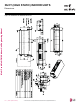
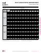
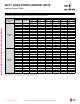
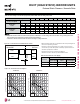
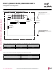
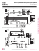
Table Of Contents

Refrigerant Flow Diagrams
LMHN240HV and LMHN360HV Refrigerant Flow Diagram.
Multi F Ceiling-Concealed Duct (High Static) Indoor Unit Refrigerant Pipe Connection Port Diameters.
Model No. Vapor (inch) Liquid (inch)
LMHN240HV Ø1/2 Ø1/4
LMHN360HV Ø5/8 Ø3/8
Multi F Ceiling-Concealed Duct (High Static) Indoor Unit Thermistor Details.
Description (Based on Cooling Mode) PCB Connector
Indoor Air Temperature Thermistor CN-ROOM
Evaporator Inlet Temperature Thermistor CN-PIPE/IN
Evaporator Outlet Temperature Thermistor CN-PIPE/OUT
Sirocco Fan
Heat exchanger
Gas pipe connection port
(flare connection)
Liquid pipe connection port
(flare connection)
Cooling
Heating
M
Thermistor for
suction air
temperature
Thermistor for
evaporator outlet
temperature
Thermistor for
evaporator inlet
temperature
DUCT (HIGH STATIC) INDOOR UNITS
Due to our policy of continuous product innovation, some specications may change without notication.
©LG Electronics U.S.A., Inc., Englewood Cliffs, NJ. All rights reserved. “LG” is a registered trademark of LG Corp.
108 | DUCT (HIGH STATIC)
Multi F and Multi F MAX Indoor Unit Engineering Manual
A