
Engineering Bulletin
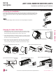
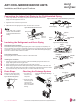
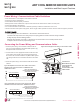
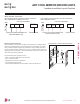
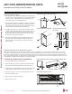
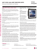
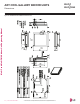
Table Of Contents
- Convergence of Technology, Innovation, Flexibility, & Style
- Unit Nomenclature
- Outdoor Unit Overview
- Indoor Unit Overview
- Controls and Options Overview
- Art Cool Mirror Indoor Units
- General Data / Specifications
- Dimensions
- Cooling Capacity Table
- Heating Capacity Table
- Acoustic Data
- Air Velocity and Temperature Distribution
- Refrigerant Flow Diagram
- Wiring Diagram
- Factory Supplied Parts and Materials
- Installation and Best Layout Practices
- Art Cool Gallery Indoor Units
- General Data / Specifications
- Dimensions
- Cooling Capacity Table
- Heating Capacity Table
- Acoustic Data
- Air Velocity and Temperature Distribution
- Refrigerant Flow Diagram
- Wiring Diagram
- Factory Supplied Parts and Materials
- Installation and Best Layout Practices
- Standard Wall-Mounted Indoor Units
- General Data / Specifications
- Dimensions
- Cooling Capacity Table
- Heating Capacity Table
- Acoustic Data
- Air Velocity and Temperature Distribution
- Refrigerant Flow Diagram
- Wiring Diagram
- Factory Supplied Parts and Materials
- Installation and Best Layout Practices
- Duct (Low Static) Indoor Units
- General Data / Specifications
- Dimensions
- Cooling Capacity Table
- Heating Capacity Table
- External Static Pressure
- Acoustic Data
- Refrigerant Flow Diagrams
- Wiring Diagram
- Factory Supplied Parts and Materials
- Installation and Best Layout Practices
- Duct (High Static) Indoor Units
- General Data / Specifications
- Dimensions
- Cooling Capacity Table
- Heating Capacity Table
- External Static Pressure / Acoustic Data
- Refrigerant Flow Diagrams
- Wiring Diagrams
- Factory Supplied Parts and Materials / Installation
- Installation and Best Layout Practices
- Four-Way Ceiling Cassette Indoor Units
- General Data / Specifications
- Dimensions
- Dimensions
- Cooling Capacity Table
- Heating Capacity Table
- Acoustic Data
- Air Velocity and Temperature Distribution
- Refrigerant Flow Diagram
- Wiring Diagram
- Factory Supplied Parts and Materials
- Installation and Best Layout Practices
- Vertical-Horizontal Indoor Units
- General Data / Specifications
- Dimensions
- Cooling Capacity Table
- Heating Capacity Table
- External Static Pressure
- Acoustic Data
- Refrigerant Flow Diagram
- Wiring Diagram
- Factory Supplied Parts and Materials
- Installation and Best Layout Practices
- Equipment Selection Procedure
- Building Ventilation Design Guide
- Placement Considerations
- Refrigerant Piping Design
- Design Guideline Summary
- Creating a Balanced System / Manual Layout Procedure
- LG Engineered Multi F MAX Y-Branch Kit
- Refrigerant Charge
- Installation & Layout Best Practices
- Refrigerant Piping System Layout
- Piping Insulation
- Condensate Drain Piping
- Y-Branch Kit
- Wiring Connections
- Power Wiring (208-230V) and Communications Cable Details
- Indoor Unit Group Control
- Acronyms

Connecting the Indoor Unit Piping to the Field-Installed Piping
If the drain hose is routed
inside a room, add insulation
to prevent condensation from
forming.
1. Center align the indoor unit piping (refrigerant and drain) and the field-installed
piping, then hand tighten the flare nut.
2. Tighten the flare nut with a torque wrench.
3. Attach the drain tube piping to the indoor unit drain hose as shown.
Indoor unit piping
Flare nutField-installed
piping
Spanner
Field-installed
piping
Flare nut
Torque
wrench
Figure 26:Drain Piping Slope.
Narrow tape
Adhesive
Drain extension
Indoor unit
drain hose
Insulating the Refrigerant and Drain Piping
Bands
Insulation
Narrow tape
Field-supplied
piping
Wide tape
Wrap with tape
Indoor unit
piping
Piping
Wrap with tape
Drain hose
Piping
Wide tape
1.
2.
3.
Figure 25:Insulating the Piping.
Drain Slope
Drain hose should point down
so water can flow away easily.
Slope Down
Figure 23:Indoor Unit to Field-Installed Piping Connection.
Checking the Drainage System
Drain pan
Drain
hose
Drain hose
connection
Check for
leaks
Check for
leaks
Figure 24:Extending the Drain Hose.
1. Pour water on
the indoor unit
evaporator.
2. Ensure the water
flows through and
out of the hose
and away from the
indoor unit without
leaking.
ART COOL MIRROR INDOOR UNITS
Installation and Best Layout Practices
Refrigerant Piping Insulation
Field-installed vapor and liquid refrigerant piping lines must be properly and completely cov-
ered in insulation (up to the indoor unit piping connections). Any exposed piping may generate
condensate or will cause burns if touched. Insulation for this field-installed refrigerant piping
must have a minimum heat resistance of 248°F.
Drain Piping Insulation
Drain piping must have insulation a minimum of 7/32 inches thick.
Installing the Insulation
1. Overlap the insulation at the connection of the field-installed piping and the indoor unit
piping. Tape together so that no gaps exist.
2. Secure insulation to the rear piping housing section with vinyl tape.
3. Bundle the piping and drain hose with tape where they meet at the back of the indoor unit
frame. Position the drain hose at the bottom of the bundle (positioning the drain hose at the
top of the bundle may cause the drain pan to overflow inside the indoor unit).
Figure 27:Checking the Drainage
System.
Due to our policy of continuous product innovation, some specications may change without notication.
©LG Electronics U.S.A., Inc., Englewood Cliffs, NJ. All rights reserved. “LG” is a registered trademark of LG Corp.
32 | ART COOL MIRROR
Multi F and Multi F MAX Indoor Unit Engineering Manual
MULTI
F
MAX
MULTI
F