
Install Instructions
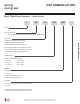
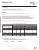
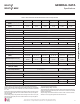
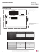
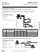
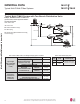
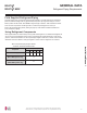
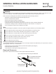
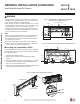
Table Of Contents
- Safety Instructions
- Introduction
- Unit Nomenclature
- General Data
- Specifications
- Typical Multi F/Multi F Max Systems
- Refrigerant Piping Requirements
- General Installation Guidelines
- Inspection
- Install Wall-Mounted IDU Chassis
- Refrigerant Piping
- Piping Materials and Handling
- Piping Preparation
- Piping Connections
- Piping Insulation
- Drain Piping
- Electrical Wiring
- Power Wiring Specifications and Best Practices
- Power Wiring Specifications and Best Practices/Controller Options
- Indoor Unit Electrical Connections Guidelines
- Indoor Unit Electrical Connections Procedure
- Self Diagnosis Functions
- LG SIMS - Self Diagnosis Functions
- Optional Wall-Mounted Sensor and Controller
- Troubleshooting
- Cautions for Refrigerant leaks
- Installation Checklist

11
Installation Manual
Due to our policy of continuous product innovation, some specifications may change without notification.
©LG Electronics U.S.A., Inc., Englewood Cliffs, NJ. All rights reserved. “LG” is a registered trademark of LG Corp.
MA
X
MUL
TI
F
MUL
TI
F
UNIT NOMENCLATURE
Multi F Multi-Zone Systems — Indoor Units
M
N 158 HVT
Generation
3 = Third (also Third Gen if no number in this position)
4 = Fourth
Features:
H = Heat Pump
V = Inverter
T = High Wall-Mounted Indoor Unit
P = Art Cool Gallery Indoor Unit
Nominal Capacity
(Nominal cooling capacity in Btu/h):
Component:
AN: Art Cool™ Wall-Mounted Indoor Unit
N: Standard Wall-Mounted Indoor Unit
CN: Four-Way Ceiling-Cassette Indoor Unit
DN: Ceiling-Concealed Duct (Low Static) Indoor Unit
HN: Ceiling-Concealed Duct (High Static) Indoor Unit
VN: Vertical-Horizontal Air Handling Indoor Unit
L = LG
078 = 7,000
090 = 9,000
120 = 12,000
158 = 15,000
180 = 18,000
248 = 24,000
L
• Voltage for all equipment is 208-230V, 60 Hz, 1-phase.
• All indoor units are compatible with wired controllers
Type: M = Multi-Zone
A/S = Single Zone (Gen 4 Single Zone units also compatible with Multi Zone)