
Specification Guide

TWO-WAY VAHU INDOOR UNITS
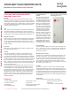
Installation and Best Layout Practices
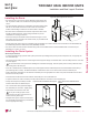
Drain Piping Specifications
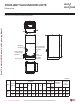
• Drain piping must have downward gradient of at
least 1/50 to 1/100; to prevent reverse flow, slope
must not be straight up and down.
•
Do not damage the drain port on the indoor unit
when connecting the field-supplied drain piping.
Drain Hole
Gaps Should Not Be Present
Unit
Drain Piping
(Field Supplied)
Drain Piping Insulation
(Field Supplied)
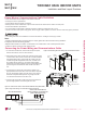
U-Trap
B
C
A
3/4-inch Connector
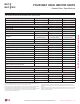
Field-Installed U-Trap Specifications
)LJXUHClose up of Drain Piping Connection.
)LJXUHInstalling the U-Trap.
7RSUHYHQWOHDNVFDXVHE\DEORFNLQWKHLQWDNHDLU¿OWHULQVWDOOD87UDS
$LQFKHV
%&
&[63
63 ([WHUQDO3UHVVXUHLQ:*
Example:
([WHUQDO3UHVVXUH LQ:*
$LQFKHV
%LQFKHV
&LQFKHV
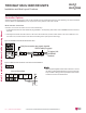
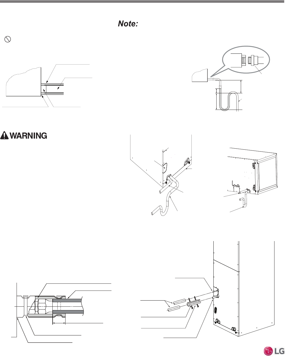
Drain Access Hole
Air Filter Cover
Main Drain with Suitable Trap. (Field-Supplied
Trap with Sufficient Depth Can Be Used.
Standard Size P-Traps Cannot Be Used.
Supplementary Drain with a
Proper Trap (Field Supplied Kit
Can Be Used)
)LJXUHVertical Primary and
Secondary Drain Layout.
)LJXUHHorizontal Primary and
Secondary Drain Layout.
Refrigerant Piping Insulation
Field-installed vapor and liquid refrigerant piping lines must
be properly and completely covered in insulation (up to the
indoor unit piping connections) and must comply with federal,
state, and local requirements. Any exposed piping will gener-
ate condensate or will cause burns if touched. Insulation for
this field-installed refrigerant piping must have a minimum heat
resistance of 248°F.
If the indoor unit is installed and is operated at an extended
period in a highly humid environment (dew point tempera-
ture >73°F), however, condensate will form. To prevent this
phenomenon, install adiabatic glass wool insulation with a
thickness of 7/16 to 13/16 inches thick. Also, install glass wool
insulation on all indoor units that are located in the ceiling
plenum.
Drain Piping Insulation
Drain piping insulation must be 7/32 inches thick, minimum.
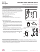
Insulating the Refrigerant and
Drain Piping
Connection for Liquid Piping
Refrigerant Piping
Insulation (Field Supplied)
Connection for Vapor Piping
Insulation Zip Tie (Field Supplied)
Refrigerant Piping Insulation (Field
Supplied)
)LJXUHClose Up of Refrigerant Piping Connection Insulation.
Gaps Should Not be Present
Overlap Piping Insulation
Refrigerant Piping Insulation (Field Supplied)
Insulation Clip (Field Supplied)
Refrigerant Piping Insulation
(Field Supplied)
)LJXUHInsulating the Refrigerant Piping and Refrigerant Piping
Connections.
Ensure all piping is insulated. Exposed piping can cause
burns if touched.
'XHWRRXUSROLF\RIFRQWLQXRXVSURGXFWLQQRYDWLRQVRPHVSHFL¿FDWLRQVPD\FKDQJHZLWKRXWQRWL¿FDWLRQ
©/*(OHFWURQLFV86$,QF(QJOHZRRG&OLIIV1-$OOULJKWVUHVHUYHG³/*´LVDUHJLVWHUHGWUDGHPDUNRI/*&RUS
152 | VERTICAL-HORIZONTAL
Multi F and Multi F MAX Indoor Unit Engineering Manual
MULTI
F
MAX
MULTI
F