
Specification Guide


Design Guideline Summary
7KHIROORZLQJDUHH[DPSOHVRIPDQXDOSLSHVL]HFDOFXODWLRQV'HVLJQHUVDUHKLJKO\HQFRXUDJHGWRXVH/$76IRU0XOWL)V\VWHPV
REFRIGERANT PIPING DESIGN
B
A
h2 IHHW
A
h3 IHHW
KIHHW
h1 IHHW
BDU Y-Branch
BDU
IDU
A
ODU
IDU
IDU
IDU
IDU
IDU
B
B
B
B
B
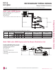
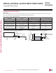
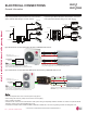
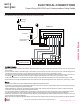
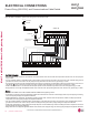
Multi F MAX with LGRED System with Two Branch Distribution Units
Example: LMU420HHV outdoor unit with
six (6) indoor units and two (2) branch
distribution units connected.
2'82XWGRRU8QLW
,'8,QGRRU8QLW
%'8%UDQFK'LVWULEXWLRQ8QLWV
Ȉ$0DLQ3LSH
Ȉ%%UDQFK3LSH%UDQFK'LVWULEXWLRQ8QLW>V@WR
Indoor Unit[s]).
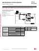
7DEOH Multi F MAX with LGRED Outdoor Unit Refrigerant Piping System Limitations.
Pipe Length
(ELF = Equivalent
Length of pipe in Feet)
7RWDOSLSLQJOHQJWKȈ$Ȉ%
IHHW
Main pipe (Outdoor Unit to
%UDQFK'LVWULEXWLRQ8QLWVȈ$
Minimum
10 feet
Maximum
IHHW
7RWDOEUDQFKSLSLQJOHQJWKȈ%
IHHW
Branch pipe (Branch Distribu-
WLRQ8QLWVWR,QGRRU8QLWV%
Minimum
10 feet
Maximum
IHHW
Elevation Differential
(All Elevation
Limitations are
Measured in Actual
Feet)
If outdoor unit is above or below indoor unit (h1)
IHHW
Between the farthest two indoor units (h2)
IHHW
Between branch distribution unit and farthest
connected indoor unit(s) (h3)
IHHW
Between branch distribution units (h4)
IHHW
7DEOH Multi F MAX with LGRED Piping Sizes.
Piping
Main Pipe A
(inch)
Branch Pipe B
Liquid Ø3/8
Depends on the size
of the indoor unit piping
Gas Ø3/4
'XHWRRXUSROLF\RIFRQWLQXRXVSURGXFWLQQRYDWLRQVRPHVSHFL¿FDWLRQVPD\FKDQJHZLWKRXWQRWL¿FDWLRQ
©/*(OHFWURQLFV86$,QF(QJOHZRRG&OLIIV1-$OOULJKWVUHVHUYHG³/*´LVDUHJLVWHUHGWUDGHPDUNRI/*&RUS
202 | DESIGN & PRACTICES
Multi F and Multi F MAX Indoor Unit Engineering Manual
MULTI
F
MAX
MULTI
F