
Specification Guide

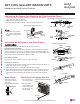


ART COOL GALLERY INDOOR UNITS
Installation and Best Layout Practices
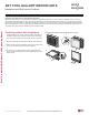
)LJXUH:LUHG&RQWUROOHU&RQQHFWLRQRQWKH,QGRRU8QLW7HUPLQDO%ORFN
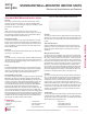
Wired Controller Connections
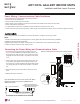
)LJXUH3URSHU/RFDWLRQIRUWKH:LUHG&RQWUROOHU
:LUHGFRQWUROOHUVLQFOXGHDVHQVRUWRGHWHFWURRPWHPSHUDWXUH7RPDLQWDLQFRPIRUW
levels in the conditioned space, the wired controller must be installed in a location
away from direct sunlight, high humidity, and where it could be directly exposed to
cold air. Controller must be installed four (4) to five (5) feet above the floor where its
LED display can be read easily, in an area with good air circulation, and where it can
detect an average room temperature.
'RQRWLQVWDOOWKHZLUHGFRQWUROOHUQHDURULQ
• Drafts or dead spots behind doors and in corners
• Hot or cold air from ducts
• Radiant heat from the sun or appliances
• Concealed pipes and chimneys
• An area where temperatures are uncontrolled, such as an outside wall
Wired Controller Placement
4 to 5 feet
above the floor
NO
NO
NO
YES
Remote Controlle r
TEMP
Remote Controlle r
TEMP
R
e
m
o
t
e
C
o
n
t
r
o
l
l
e
r
T
E
M
P
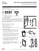
Hanging the Wired Controller
1. The controller wiring/cable can be installed in one of three direc-
WLRQVWRSEDFNRURQWKHULJKWVLGH,IWRSRUULJKWVLGHLQVWDOODWLRQ
is desired, remove cable guide grooves on the controller, and
then position wiring/cable on applicable side.
2. Choose and mark the area of installation, and then screw the wall
plate into place (using the provided parts). Install the controller
wall plate to fit the electrical box if one is present. Ensure that no
gaps exist between the wall plate and the wall itself.
3. Arrange wiring/cables so as not to interfere with the controller
circuitry. Position the wired controller on the wall plate. Snap into
place by pressing the bottom part of the wired controller onto
the wall plate. Make sure that no gaps exist between the wired
controller and the wall plate on all sides.
4. To remove wired controller from the wall plate, insert a screw-
driver into the two holes at the bottom. Twist screwdriver to
release controller.
Do not damage the controller components
when removing.
Back
Top
Top
Right
Side
Right
Side
Wall Wall
Wall Wall
Installing the Controller
Removing the Controller
)LJXUHRemoving the Cable Guide Grooves.
)LJXUH$WWDFKLQJWKH:DOO3ODWH
)LJXUHInstalling/Removing the
Controller.
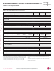
Indoor Unit Terminal Block
1(L1 ) 2(L2)
GND
GRN / YLW
BR
BL
RD
CN-REMO
To Outdoor Unit or Branch Distribution Unit
(Multi F MAX Systems Only)
To Wired Controller
3
ART COOL GALLERY™ | 45
Art Cool Gallery™
'XHWRRXUSROLF\RIFRQWLQXRXVSURGXFWLQQRYDWLRQVRPHVSHFL¿FDWLRQVPD\FKDQJHZLWKRXWQRWL¿FDWLRQ
©/*(OHFWURQLFV86$,QF(QJOHZRRG&OLIIV1-$OOULJKWVUHVHUYHG³/*´LVDUHJLVWHUHGWUDGHPDUNRI/*&RUS
MULTI
F
MAX
MULTI
F