MULTI F MULTI F MAX WITH HEAT PUMP OUTDOOR UNIT INSTALLATION MANUAL Multi-Zone Heat Pump Systems 1.5 to 3.
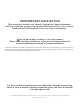
PROPRIETARY DATA NOTICE This document, as well as all reports, illustrations, data, information, and other materials are the property of LG Electronics U.S.A., Inc., and are disclosed by LG Electronics U.S.A., Inc. only in confidence. Do not throw away, destroy, or lose this manual. Please read carefully and store in a safe place for future reference. Content familiarity is required for proper installation.
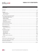
MULTI F WITH MULTI F MAX TABLE OF CONTENTS Safety Instructions ...................................................................................................................................................................................................... 4-7 Nomenclature.................................................................................................................................................................................................................. 8 General Data ......
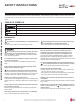
MULTI F WITH MULTI F MAX SAFETY INSTRUCTIONS MULTI F / MULTI F MAX with LGRED Outdoor Unit Installation Manual The instructions below must be followed to prevent product malfunction, property damage, injury or death to the user or other people. Incorrect operation due to ignoring any instructions will cause harm or damage. The level of seriousness is classified by the symbols described below.
MULTI F WITH MULTI F MAX SAFETY INSTRUCTIONS Installation, continued Properly insulate all cold surfaces to prevent “sweating.” Cold surfaces such as uninsulated piping can generate condensate that could drip, causing a slippery surface that creates a risk of slipping, falling, and personal injury. CAUTION Be very careful when transporting the product. There is a risk of the product falling and causing physical injury.
MULTI F WITH MULTI F MAX SAFETY INSTRUCTIONS Wiring DANGER MULTI F / MULTI F MAX with LGRED Outdoor Unit Installation Manual High voltage electricity is required to operate this system. Adhere to the NEC code and these instructions when wiring. Improper connections and inadequate grounding can cause accidental injury or death. Always ground the unit following local, state, and NEC codes. 7KHUH LV ULVN RI ¿UH HOHFWULF VKRFN DQG SK\VLFDO LQMXU\ RU GHDWK 7XUQ WKH SRZHU Rႇ DW WKH QHDUHVW GLVFRQQHFW E
MULTI F WITH MULTI F MAX SAFETY INSTRUCTIONS Operation DANGER 'R QRW SURYLGH SRZHU WR RU RSHUDWH WKH XQLW LI LW LV ÀRRGHG or submerged. 7KHUH LV ULVN RI ¿UH HOHFWULF VKRFN SK\VLFDO LQMXU\ RU GHDWK Use a dedicated breaker for this product. 7KHUH LV ULVN RI ¿UH HOHFWULF VKRFN SK\VLFDO LQMXU\ RU GHDWK Do not operate the disconnect switch with wet hands. 7KHUH LV ULVN RI ¿UH HOHFWULF VKRFN SK\VLFDO LQMXU\ RU GHDWK Periodically verify the equipment mounts have not deteriorated.
MULTI F WITH MULTI F MAX UNIT NOMENCLATURE Multi-Zone Systems — Indoor Units and Outdoor Units MULTI F / MULTI F MAX with LGRED Outdoor Unit Installation Manual L M DN 12 6 HV 36 2 0 L = LG Type: M = Multi-Zone Component: AN: Art Cool™ Wall-Mounted Indoor Unit N: Standard Wall-Mounted Indoor Unit CN: Four-Way Ceiling-Cassette Indoor Unit DN: Ceiling-Concealed Duct (Low Static) Indoor Unit HN: Ceiling-Concealed Duct (High Static) Indoor Unit VN: Vertical-Horizontal Air Handling Indoor Unit U: Ou
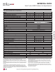
MULTI F WITH MULTI F MAX GENERAL DATA 0XOWL ) ZLWK /*5(' 2XWGRRU 8QLW 6SHFL¿FDWLRQV 1 Rated capacity applied with non-ducted indoor units, and is rated 0 ft. above sea level with 25 ft. of refrigerant line per indoor unit and a 0 ft. level difference between outdoor and indoor units. All capacities are net with a combination ratio between 95 – 105%.
MULTI F WITH MULTI F MAX GENERAL DATA Multi F with LGRED Outdoor Unit Electrical Data MULTI F / MULTI F MAX with LGRED Outdoor Unit Installation Manual Table 2: Multi F with LGRED Electrical Data. Nominal Tons Unit Model No. 1.5 2 2.5 LMU180HHV LMU240HHV LMU300HHV Range Compressor Compressor Hertz Voltage Voltage (Min. to Max.) MCA MOP RFA Quantity Motor RLA 60 208 - 230 Voltage tolerance is ±10%. Maximum allowable voltage unbalance is 2%. MCA = Minimum Circuit Ampacity.
MULTI F WITH MULTI F MAX GENERAL DATA Multi F with LGRED Outdoor Unit Dimensions Figure 1: LMU180HHV, LMU240HHV, and LMU300HHV External Dimensions. Unit: Inch Gravity point Product Data No. Part Name 1 Air discharge grille 2 Gas pipe connection 3 Liquid pipe connection 4 Main service valve (Liquid) 5 Main service valve (Gas) Due to our policy of continuous product innovation, some specifications may change without notification. ©LG Electronics U.S.A., Inc., Englewood Cliffs, NJ.
GENERAL DATA MULTI F / MULTI F MAX with LGRED Outdoor Unit Installation Manual 0XOWL ) 0$; ZLWK /*5(' 2XWGRRU 8QLW 6SHFL¿FDWLRQV MULTI F WITH MULTI F MAX Table 3: 0XOWL ) 0$; ZLWK /*5(' 2XWGRRU 8QLW 6SHFL¿FDWLRQV Model Number LMU360HHV LMU420HHV Capacity Nominal 36,000 42,000 Cooling (Btu/h) (Min.~Rated~ Max.)1 11,700~36,000~46,733 11,700~42,000~53,897 Cooling Power Input (kW) (Min.~Rated~ Max.) 0.72 ~ 2.40 ~ 3.75 0.72 ~ 3.00 ~ 4.34 Cooling Running Current (A) (Min.~Rated~ Max.) 3.9 ~ 13.0 ~ 20.4 3.
MULTI F WITH MULTI F MAX GENERAL DATA Multi F MAX with LGRED Outdoor Unit Electrical Data Table 4: Multi F MAX with LGRED Electrical Data. Voltage Nominal Unit Model Hertz Voltage Compressor Range MCA MOP Compressor Tons No. Quantity Motor RLA (Min. to Max.) 3.0 3.5 LMU360HHV 60 208 - 230 LMU420HHV Voltage tolerance is ±10%. Maximum allowable voltage unbalance is 2%. MCA = Minimum Circuit Ampacity. 187 - 253 30.2 30.2 45 45 1 1 20.4 20.
MULTI F WITH MULTI F MAX GENERAL DATA Multi F with LGRED Outdoor Unit Dimensions Figure 2: LMU360HHV and LMU420HHV External Dimensions. 6-5/8 13 14-3/16 15-3/4 Part Name No. 6-1/2 6-1/2 24-13/32 1 Liquid pipe connection 2 Gas pipe connection 3 Air discharge grille 4 Power & transmission connection 4 14-1/20 37-13/32 14 Due to our policy of continuous product innovation, some specifications may change without notification. ©LG Electronics U.S.A., Inc., Englewood Cliffs, NJ.
MULTI F WITH MULTI F MAX GENERAL DATA %UDQFK 'LVWULEXWLRQ 8QLW 6SHFL¿FDWLRQ (OHFWULFDO 'DWD Table 5: Branch Distribution Unit General Data. Model Number No. of Connectible Indoor Units1 Max. Nominal Capacity / Port (Btu/h)2 Max. Nominal Capacity / Branch Distribution Unit (Btu/h) Operation Temperature Range (°F DB) Unit Data Refrigerant Type Power Supply V, Ø, Hz Power Input (W) Rated Amps (A) Dimensions W x H x D (in.) Maximum Total System Piping (ft.
MULTI F WITH MULTI F MAX GENERAL DATA Branch Distribution Unit Dimensions A-C (and PMBD3640 D) Connections: Liquid Pipe Ø1/4 Gas Pipe Ø3/8 PMBD3641 D Connections: Liquid Pipe Ø1/4 Gas Pipe Ø1/2 Unit: Inch 9-27/32 13-9/32 A B C D Ø3/4 11-23/32 Indoor Unit Piping Direction Ø3/8 9-21/32 Minimum 15-3/4 Minimum 15-3/4Mininum 15-3/4 1-31/32 1-31/32 Minimum 24 Mininum 3-15/16 Minimum 12 Side View Notes: 1. For PMBD3620 Unit, Ports A and B are Available. 2.
MULTI F WITH MULTI F MAX 75$163257,1* /,)7,1* 7UDQVSRUWLQJ /LIWLQJ WKH 2XWGRRU Unit • At the time of delivery, the package must be checked for any damage (exterior and interior). Report any damage to the carrier claims agent immediately. • When lifting the unit, use lifting straps and place properly around the unit. • Always lift the unit using properly sized lifting straps rated to carry the unit weight. • (QVXUH WKH VWUDSV DUH ORQJ HQRXJK WR PDLQWDLQ D PD[LPXP RI D angle.
PLACEMENT CONSIDERATIONS Selecting the Best Location for the Outdoor Unit MULTI F WITH MULTI F MAX Selecting the Best Location for the Outdoor Unit MULTI F / MULTI F MAX with LGRED Outdoor Unit Installation Manual • DANGER Do not install the unit in an area where combustible gas may generate, flow, stagnate, or leak. These conditions can cause a fire, resulting in bodily injury or death.
MULTI F WITH MULTI F MAX PLACEMENT CONSIDERATIONS Selecting the Best Location for the Outdoor Unit Planning for Snow and Ice, continued. When deciding on a location to place the outdoor unit, be sure to choose an area where run-off from defrost will not accumulate and freeze on sidewalks or driveways, which may create unsafe conditions. Properly install and insulate any drain hoses to prevent the hose from freezing, cracking, leaking, and causing unsafe conditions from frozen condensate.
MULTI F WITH MULTI F MAX PLACEMENT CONSIDERATIONS Selecting the Best Location for the Outdoor Unit MULTI F / MULTI F MAX with LGRED Outdoor Unit Installation Manual Minimum Allowable Clearance and Service Access Requirements Proper clearance for the outdoor unit coil is critical for proper operation. When installing the outdoor unit, consider service, inlet and outlet, and minimum allowable space requirements as illustrated in the diagrams on the following pages.
MULTI F WITH MULTI F MAX PLACEMENT CONSIDERATIONS Selecting the Best Location for the Outdoor Unit Multi F MAX with LGRED Outdoor Unit (36,000 and 42,000 Btu/h Capacity) Service Access and Allowable Clearances When installing the outdoor unit, consider service, inlet, and outlet, and minimum allowable space requirements as illustrated in the following diagrams.
MULTI F WITH MULTI F MAX PLACEMENT CONSIDERATIONS Selecting the Best Location for the Outdoor Unit Clearance Requirements when Different Obstacles are Present, continued. (Unit: Inch) Where there are obstacles on both suction and discharge sides (discharge side obstacle is higher than the outdoor unit). Min imu m2 0" Where there are obstacles on both suction and discharge sides (discharge side obstacle is lower than the outdoor unit).
MULTI F WITH MULTI F MAX PLACEMENT CONSIDERATIONS Selecting the Best Location for the Outdoor Unit Installing Outdoor Units Indoors LG Multi F / Multi F MAX with LGRED outdoor units are engineered to be mounted outdoors and include technology designed to minimize the negative effects of winter weather’s freezing rain, sleet, and snow. Some building projects, however, necessitate placing the HVAC outdoor units indoors: • Lack of ground space.
MULTI F WITH MULTI F MAX PLACEMENT CONSIDERATIONS MULTI F / MULTI F MAX with LGRED Outdoor Unit Installation Manual Selecting the Best Location for the Outdoor Unit Provide a means to drain the condensate generated during heating mode and defrost cycle in addition to rainwater that infiltrates the inlet louver enclosed area. • Install a field-provided drain pan under the outdoor units and provide a path to a nearby floor drain.
MULTI F WITH MULTI F MAX PLACEMENT CONSIDERATIONS Selecting the Best Location for the Outdoor Unit Open Rate by Louver Radian Figure 8: Open Rate by Louver Radian Formula.
PLACEMENT CONSIDERATIONS 6HOHFWLQJ WKH %HVW /RFDWLRQ IRU WKH ,QGRRU 8QLWV MULTI F WITH MULTI F MAX Branch Distribution Units Select a location for installing the indoor units that will meet the following conditions: • Within allowable parameters for proper connection to the outdoor unit (and branch distribution unit, if a Multi F MAX with LGRED system). • So that condensation drainage can be conveniently routed away.
MULTI F WITH MULTI F MAX PLACEMENT CONSIDERATIONS Selecting the Best Location for the Branch Distribution Units A-C (and PMBD3640 D) Connections: Liquid Pipe Ø1/4 Gas Pipe Ø3/8 PMBD3641 D Connections: Liquid Pipe Ø1/4 Gas Pipe Ø1/2 9-27/32 13-9/32 A B C D Ø3/4 11-23/32 Indoor Unit Piping Direction Unit: Inch Ø3/8 9-21/32 Minimum 15-3/4 Minimum 15-3/4Mininum 15-3/4 1-31/32 1-31/32 1-31/32 1-31/32 1-31/32 Controller Service Service Space Minimum 24 Mininum 3-15/16 Mininum 1-3/16 2-7/32
MULTI F WITH MULTI F MAX 0RXQWLQJ $QFKRULQJ WKH 2XWGRRU 8QLW *HQHUDO Specifications Figure 11: Example of Using an Insert for a Hole in a Reinforced Concrete Beam. Outdoor Unit Platform Concrete Specifications • • • • Polyblock / Anti-Vibration Material Insert • Tightly anchor the outdoor unit with a bolt and nut to a concrete or rigid platform. • :KHQ LQVWDOOLQJ RQ D ZDOO ZLWK ¿HOG VXSSOLHG EUDFNHWV URRI RU URRIWRS VHFXUHO\ DQFKRU WKH PRXQWLQJ platform with nails and / or wiring, taking into
MULTI F WITH MULTI F MAX 02817,1* $1&+25,1* THE BRANCH DISTRIBUTION UNITS Branch Distribution Unit Orientation Multi F MAX with LGRED branch distribution (BD) units can be installed in a multitude of options to fit various building configurations and job or application requirements (suspended from the ceiling or mounted on the wall).
MULTI F WITH MULTI F MAX 02817,1* $1&+25,1* THE BRANCH DISTRIBUTION UNITS Wall Mount Installation - Hangers Only Figure 19: Acceptable Branch Distribution Unit Wall Mount Orientations. Wall Mounting Options Wall Wall Wall PCB PCB Bottom of Unit Bottom of Unit PCB MULTI F / MULTI F MAX with LGRED Outdoor Unit Installation Manual 1. Attach the factory-supplied hangers with two (2) screws each at the designated four (4) areas on the frame of the BD unit. 2.
MULTI F WITH MULTI F MAX LG AIR CONDITIONER TECHNICAL SOLUTION (LATS) LG Air Conditioner Technical Solution (LATS) Software A properly designed and installed refrigerant piping system is critical to the optimal performance of LG air-conditioning systems. To assist engineers, LG offers, free of charge, LG Air Conditioner Technical Solution (LATS) software—a total design solution for LG air conditioning systems.
LG AIR CONDITIONER TECHNICAL SOLUTION (LATS) MULTI F WITH MULTI F MAX MULTI F / MULTI F MAX with LGRED Outdoor Unit Installation Manual LATS Generates a Complete Project Report LATS software also generates a report containing project design parameters, cooling and heating design data, system component performance, and capacity data.
MULTI F WITH MULTI F MAX 5()5,*(5$17 6$)(7< 67$1'$5'6 DEVICE CONNECTION LIMITATIONS Refrigerant Safety Standards Device Connection Limitations • The minimum number of connected and operating indoor units to Multi F / Multi F MAX with LGRED systems is two, taking into consideration the minimum combination ratio. • The maximum number of indoor units for each Multi F / Multi F MAX with LGRED heat pump system is: LMU180HHV = 2 LMU240HHV = 3 LMU300HHV = 4 LMU360HHV = 5 LMU420HHV = 6 )RU DOORFDWHG FDSDFLW\
MULTI F WITH MULTI F MAX 5()5,*(5$17 6$)(7< 67$1'$5'6 DEVICE CONNECTION LIMITATIONS Figure 23: Multi F MAX Refrigerant Piping System Limitations. Table 12: Multi F MAX with LGRED Outdoor Unit Refrigerant Piping System Limitations. 7RWDO SLSLQJ OHQJWK ȉ$ ȉ% IHHW Minimum 9.
MULTI F WITH MULTI F MAX SELECTING COPPER PIPING Selecting Field-Supplied Copper Piping Always follow local codes when selecting and installing copper pipe and piping system components. Approved piping for use with Multi F / MAX with LGRED products will be marked “R410 RATED” along the length of the pipe. Piping wall thickness must meet local code requirements and be approved for a maximum operating pressure of 551 psi.
MULTI F WITH MULTI F MAX COPPER EXPANSION AND CONTRACTION MULTI F / MULTI F MAX with LGRED Outdoor Unit Installation Manual Copper Expansion and Contraction Under normal operating conditions, the vapor pipe temperature of D 0XOWL ) ZLWK /*5(' V\VWHP FDQ YDU\ DV PXFK DV ) :LWK WKLV large variance in pipe temperature, the designer must consider pipe expansion and contraction to avoid pipe and fitting fatigue failures.
MULTI F WITH MULTI F MAX COPPER EXPANSION AND CONTRACTION To find the anticipated expansion value: 1. From the table below, find the row corresponding with the actual feet of the straight pipe segment. 2. Estimate the minimum and maximum temperature of the pipe. 3. In the column showing the minimum pipe temperature, look up the anticipated expansion distance corresponding to the segment length. Do the same for the maximum pipe temperature. 4. Calculate the difference in the two expansion distance values.
MULTI F WITH MULTI F MAX COPPER EXPANSION AND CONTRACTION Figure 24: Coiled Expansion Loops and Offsets (Plan View). L MULTI F / MULTI F MAX with LGRED Outdoor Unit Installation Manual L R L R Large Tubing U-bend (>3/4 in.) Loop Small Tubing U-bend (<3/4 in.) All expansion loops and offsets must be installed in the horizontal plane to prevent the possibility of trapping oil. Loops and offsets in vertical risers must also be installed in a horizontal plane.
MULTI F WITH MULTI F MAX PIPING HANDLING Piping Handling Keep Pipes Capped While Storing. Pipes used for the refrigerant piping system must include the specified thickness, and the interior must be clean. While handling and storing, do not bend or damage the pipes, and take care not to contaminate the interior with dust, moisture, etc. No moisture should be inside the piping. Moisture Possible - Significant hydrolysis of refrigerant oil. Problems - Refrigerant oil degradation.
REFRIGERANT SYSTEM ENGINEERING MULTI F WITH MULTI F MAX MULTI F / MULTI F MAX with LGRED Outdoor Unit Installation Manual Proper system operation depends on the installer using utmost care while assembling the piping system. The following pages are an overview of best practices when installing the refrigerant piping system. LG Electronics U.S.A.,Inc.
MULTI F WITH MULTI F MAX REFRIGERANT SYSTEM ENGINEERING Obstacles Figure 25: Installing Piping Above and Below an Obstacle. When an obstacle, such as an I-beam or concrete T, is in the path of the planned refrigerant pipe run, it is best practice to route the pipe over the obstacle. If adequate space is not available to route the insulated pipe over the obstacle, then route the pipe under the obstacle.
REFRIGERANT SYSTEM ENGINEERING MULTI F WITH MULTI F MAX Examples of Supports Figure 31: U-Bolt Support with Insulation. Figure 32: O-Ring Support with Insulation. Figure 33: Saddle-Type Support. Bolt Support at Intervals Between 5 and 6-3/4 Feet MULTI F / MULTI F MAX with LGRED Outdoor Unit Installation Manual Insulation Bolt 1.5t Plate PVC PVC Do not compress the insulation with the saddle-type support.
MULTI F WITH MULTI F MAX REFRIGERANT SYSTEM ENGINEERING Pipe Sleeves at Penetrations LG requires that all pipe penetrations through walls, floors, and pipes buried underground be properly insulated and routed through an appropriate wall sleeve of sufficient size to prevent compression of refrigerant pipe insulation and promote free movement of the pipe within the sleeve. Use 4"+ curved sheet metal saddles between the bottom surface of the pipe and the bottom surface of the penetration.
FLARING AND BRAZING PROCEDURES MULTI F WITH MULTI F MAX Flaring and Brazing Procedures MULTI F / MULTI F MAX with LGRED Outdoor Unit Installation Manual One of the main causes of refrigerant leaks is a defective connection. For LG HVAC systems, the installer needs to know how perform both flared and brazed connections successfully. • During installation, it is imperative to keep the piping system free of contaminants and debris such as copper burrs, slag, or carbon dust.
MULTI F WITH MULTI F MAX FLARING AND BRAZING PROCEDURES Tightening the Flare Nuts Tightening Torque for Flare Nuts. Pipe Size (in. O.D.) Outside Diameter (mm) Tightening Torque (ft-lbs.) 13.0 - 18.0 1/4 6.35 9.52 24.6 - 30.4 3/8 39.8 - 47.7 1/2 12.7 45.4 - 59.3 15.88 5/8 71.5 - 87.5 19.05 3/4 Do not use polyolyester (POE) or any other type of mineral oil as a thread lubricant.
MULTI F WITH MULTI F MAX INSTALLING MULTI F WITH LGRED SYSTEMS Multi F with LGRED Outdoor Unit to Indoor Unit Piping Connections MULTI F / MULTI F MAX with LGRED Outdoor Unit Installation Manual Avoid Pipe Damage • When routing field-provided piping, avoid damaging the outdoor unit from excessive vibration. • Properly insulate the liquid and gas lines separately up to the point of connection at the unit frame. • See table below for Multi F with LGRED outdoor unit connection types.
MULTI F WITH MULTI F MAX INSTALLING MULTI F WITH LGRED SYSTEMS Installing Field Piping to the Outdoor Unit Piping Connections Refrigerant Piping System Installation 1. Verify the outdoor unit service ports are closed. 2. Remove the caps on the outdoor unit piping connections. 3. Connect the gas piping first to ROOM A, then to ROOM B, then to ROOM C, in that order. Number of connections will differ depending on outdoor unit. 4.
MULTI F WITH MULTI F MAX INSTALLING MULTI F MAX WITH LGRED SYSTEMS MULTI F / MULTI F MAX with LGRED Outdoor Unit Installation Manual 0XOWL ) 0$; ZLWK /*5(' 5HIULJHUDQW 3LSLQJ &RQQHFWLRQV 3LSLQJ 5RXWHV For Multi F MAX with LGRED outdoor units, piping can be installed in one of four directions: front, rear, right, and bottom. Whatever direction is chosen, plug the access holes with field-provided putty or insulation to fill all gaps.
MULTI F WITH MULTI F MAX INSTALLING MULTI F MAX WITH LGRED SYSTEMS Branch Distribution to Indoor Unit Piping Connections • Install indoor unit liquid and vapor refrigerant pipes (and connection wiring) to the appropriate branch distribution ports. • Clearly note on the indoor unit’s refrigerant piping (liquid, vapor) which branch distribution port it is connected to (A, B, C, D). Figure 50: Branch Distribution Piping Connections.
MULTI F WITH MULTI F MAX INSTALLING MULTI F MAX WITH LGRED SYSTEMS MULTI F / MULTI F MAX with LGRED Outdoor Unit Installation Manual Installing Field Piping to the Branch Distribution Unit Piping Connections 1. Remove any caps, etc., that may be on the branch distribution unit. 2. Tighten each piping connection individually following the “Tightening the Flare Nuts” procedure below. 3.
MULTI F WITH MULTI F MAX INSTALLING MULTI F MAX WITH LGRED SYSTEMS Figure 54: Socket Connection. Figure 55: Possible Outdoor Unit or Branch Distribution Unit to Indoor Unit Connections. 1. 3/8 in. to 3/8 in. Connection Flare side to indoor unit Ø3/8 in. 2. 3/8 in. to 1/2 in. Connection Piping Flare nut Refrigerant Piping System Installation Flare side to indoor unit Ø1/2 in. Piping Ø3/8 in. Flare nut Connection socket Ø3/8 in.
MULTI F WITH MULTI F MAX INSTALLING MULTI F MAX WITH LGRED SYSTEMS MULTI F / MULTI F MAX with LGRED Outdoor Unit Installation Manual Multi F MAX with LGRED Y-Branch Kit PMBL5620 The LG-supplied Y-Branch kit PMBL5620 MUST be used when installing two (2) branch distribution units in parallel on one (1) Multi F MAX with LGRED system. Field-supplied fittings are not permitted. Each Y-Branch kit includes two (2) Y-branches (one for the liquid line and one for the vapor line) and insulation covers.
MULTI F WITH MULTI F MAX BUNDLING AND SPECIAL APPLICATIONS Bundling Indoor unit pipe Connection pipe Vinyl tape (wide) Wrap with vinyl tape Connecting cable Pipe Refrigerant Piping System Installation If a conduit or piping set cover is not used on the connection from the outdoor unit to the interior, bundle both insulated refrigerant pipes, the drain hose, and outdoor unit to indoor unit / branch distribution unit communication / connection (power) cable together with wide vinyl tape. 1.
MULTI F WITH MULTI F MAX CONDENSATE DRAIN PIPING Outdoor Unit Condensate Drain Piping MULTI F / MULTI F MAX with LGRED Outdoor Unit Installation Manual Outdoor unit requires condensate drain piping. Condensate drain pipe must be constructed with materials approved by local code. See pages 20 to 22 for information in reference to outdoor unit placement and condensate drainage. Figure 62: Properly Insulating the Drainage Piping.
MULTI F WITH MULTI F MAX INSULATION )RU LQIRUPDWLRQ UHJDUGLQJ LQVXODWLRQ IRU XQGHUJURXQG RU SHQHWUDWLRQ VLWXDWLRQV VHH WKH ³*HQHUDO 5HIULJHUDQW 3LSLQJ 6\VWHP ,QIRUPDWLRQ´ VHFWLRQ General Piping System Insulation All refrigerant piping from the outdoor unit to the indoor units / branch distribution units (Multi F MAX with LGRED systems only) must be insulated correctly for safety and usage.
MULTI F WITH MULTI F MAX INSULATION MULTI F / MULTI F MAX with LGRED Outdoor Unit Installation Manual Minimum Refrigerant Pipe Ethylene Propylene Diene Methylene (EPDM) Insulation Wall Thickness Requirements • Do not insulate gas and liquid pipes together as this can result in pipe leakage and malfunction due to extreme temperature fluctuations. • Always properly insulate the piping. Insufficient insulation will result in condensation, reduced heating/cooling performance, etc.
MULTI F WITH MULTI F MAX INSULATION • Do not insulate gas and liquid pipes together as this can result in pipe leakage and malfunction due to extreme temperature fluctuations. • Be sure to fully insulate the piping connections. Installing the Insulation 1. Insulation material must be longer than the refrigerant piping. Each vapor and liquid piping must be insulated separately. 2.
ELECTRICAL MULTI F / MULTI F MAX with LGRED Outdoor Unit Installation Manual General Information • All power (line voltage) wiring and communication cable installation must be performed by trained service providers working in accordance with all local, state, and National Electrical Code (NEC) / UL / ETL federal regulations related to electrical equipment and wiring, and following the manufacturer product diagrams, requirements, and instructions in this manual.
ELECTRICAL &RQQHFWLRQV DQG 6SHFL¿FDWLRQV Best practice dictates using solderless ring or fork terminals at all power wiring and communication cable terminations. Use copper bearing ring or fork terminals; do not use galvanized or nickel plate over steel. Use appropriate crimping tool to attach the ring or fork terminals at all power wiring and control cable terminations. To Install a Ring or Fork Terminal: 1.
ELECTRICAL &RQQHFWLRQV DQG 6SHFL¿FDWLRQV MULTI F / MULTI F MAX with LGRED Outdoor Unit Installation Manual LG Terminal Connections Figure 76: JIS Screws. LG uses a “JIS” type of screw for all terminals; use a JIS screwdriver to tighten and loosen these screws and avoid damaging the terminal. Do not over tighten the connections — over tightening may damage the terminals — but firmly and securely attach the wiring in a way to prevent external forces from being imparted to the terminal block.
ELECTRICAL &RQQHFWLRQV DQG 6SHFL¿FDWLRQV &RPPXQLFDWLRQ &RQQHFWLRQ 3RZHU &DEOH 6SHFLILFDWLRQV • Use a conduit for the communications / connection (power) cable from the outdoor unit to the indoor units and branch distribution unit(s). Electrical interference my cause product malfunction.
ELECTRICAL Installation Figure 82: Multi F with LGRED LMU180HHV System Power Wiring and Communications Cable Connections.
ELECTRICAL Installation Figure 83: Multi F with LGRED LMU240HHV System Power Wiring and Communications Cable Connections.
ELECTRICAL Installation Figure 84: Multi F with LGRED LMU300HHV System Power Wiring and Communications Cable Connections.
ELECTRICAL Installation Figure 85: Multi F MAX with LGRED LMU360HHV and LMU420HHV System Power Wiring and Communications Cable Connections.
ELECTRICAL Installation MULTI F / MULTI F MAX with LGRED Outdoor Unit Installation Manual &RQQHFWLQJ WKH &RPPXQLFDWLRQV &RQQHFWLRQ 3RZHU &DEOH WR ,QGRRU 8QLWV 1. 2. 3. 4. 5. 6. Detach the outdoor unit panel by loosening the screws. Remove the control cover (if applicable) by loosening the screws. Remove the conduit knock outs or access holes. After securing the conduit to the panel, install a nut to the opposite side of the panel.
ELECTRICAL Installation Figure 89: Detailed Diagrams of Outdoor Unit PCB Terminal Connections. LMU240HHV (24kBtu/h) LMU180HHV (18kBtu/h) Electrical System Installation LMU300HHV (30kBtu/h) LMU360HHV (36kBtu/h) and LMU420HHV (42kBtu/h) Due to our policy of continuous product innovation, some specifications may change without notification. ©LG Electronics U.S.A., Inc., Englewood Cliffs, NJ. All rights reserved. “LG” is a registered trademark of LG Corp.
ELECTRICAL Installation &RQQHFWLQJ WKH &RPPXQLFDWLRQV &RQQHFWLRQ 3RZHU &DEOH WR WKH %UDQFK Distributor Unit (Multi F MAX with LGRED Systems Only) MULTI F / MULTI F MAX with LGRED Outdoor Unit Installation Manual General Instructions • Always connect power wiring / communications cable matching the branch distribution unit terminals to their respective indoor units (Example for three-port branch distribution unit PMBD3630: A, B, and C).
ELECTRICAL Installation PI-485 PI-485 V-net Control Integration Board for Outdoor Units adapt Multi F / Multi F MAX with LGRED systems to a LG VRF system central protocol for integration with LG central controllers. The PI-485 is installed in the Multi F / Multi F MAX with LGRED outdoor unit. For more information on PI-485 installation, see the PI-485 installation manual. Figure 92: PI-485 Board (Appearance may differ depending on model).
ELECTRICAL Installation • Communication cable from indoor unit to remote controller(s) is to be 22 AWG, 3-conductor, twisted, stranded, unshielded. Wiring must comply with all applicable local and national codes. • ,I XVLQJ WKH /* &RQWUROOHU ([WHQVLRQ FDEOH DQG WKH OHQJWK QHHGV WR EH IXUWKHU H[WHQGHG WKH /* ([WHQVLRQ .LW VROG VHSDUDWHO\ PXVW EH used. A maximum of four (4) kits (up to 165 feet) can be used. • Remote controllers have hardwired connections: SIG - 12V - GND (Comm.) terminals.
ELECTRICAL Installation Between Multiple Indoor Units Operating as a Group (Group Control) If any indoor units were specified to operate in unison: • Before running cable, decide which indoor unit will be the “Master.” The other indoor units in that group will be designated as “Slave(s).” The zone controller will be connected to the “Master.” • Set the pertinent DIP switch at each indoor unit to identify the Master and Slave(s).
MULTI F WITH MULTI F MAX FINAL INSTALLATION PROCEDURES 7ULSOH /HDN 3UHVVXUH 7HVW MULTI F / MULTI F MAX with LGRED Outdoor Unit Installation Manual 7ULSOH /HDN 3UHVVXUH 7HVW After the refrigerant piping installation is complete, perform a triple leak / pressure test.
MULTI F WITH MULTI F MAX FINAL INSTALLATION PROCEDURES 7ULSOH /HDN 3UHVVXUH DQG 'HHS (YDFXDWLRQ 7HVWV Triple Leak / Pressure Check Procedure, continued. The bubble solution must be a solution designed for refrigerant leak testing. Common soap solution must never be used on refrigerant piping as those contain chemicals that could corrode copper and brass, and cause product malfunction. 7. If the pressure does NOT drop for one (1) hour, the system passes the test. 8.
MULTI F WITH MULTI F MAX FINAL INSTALLATION PROCEDURES 'HHS (YDFXDWLRQ 7ULSOH (YDFXDWLRQ 7HVWV Deep Evacuation Procedure, continued. Figure 99: Evacuation Procedure Diagram. MULTI F / MULTI F MAX with LGRED Outdoor Unit Installation Manual 3. (YDFXDWH WR VWDWLF PLFURQ OHYHO IRU DW OHDVW RQH KRXU 4.
MULTI F WITH MULTI F MAX FINAL INSTALLATION PROCEDURES 7ULSOH (YDFXDWLRQ 7HVW Triple Evacuation Procedure Steps 1. If this procedure is performed shortly after the leak / pressure test, the cap and core on the liquid and gas (vapor) suction Schrader ports must have already been removed, and the manifold must already be connected. If the procedure was not performed shortly after the leak / pressure test, make sure to remove the cap and core on the liquid and gas (vapor) suction Schrader ports.
MULTI F WITH MULTI F MAX FINAL INSTALLATION PROCEDURES MULTI F / MULTI F MAX with LGRED Outdoor Unit Installation Manual Refrigerant Charge LG Multi F and Multi F MAX with LGRED outdoor units ship from the factory with a charge of R410A refrigerant. A trim charge may need to be added to take into account additional piping length. To determine the additional refrigerant that is needed, apply the formulas below, and record the results.
MULTI F WITH MULTI F MAX FINAL INSTALLATION PROCEDURES Refrigerant Charge Multi F MAX with LGRED Systems Additional charge (lbs.) = (Total Main Piping Length [A] - Chargeless Pipe Length of Main Pipe [L]) x a + (Installed Length of Branch [B1] – Chargeless Pipe Length [B]) x b + (Installed Length of Branch [B2] – Chargeless Pipe Length [B]) x b + (Installed Length of Branch [B3] – Chargeless Pipe Length [B]) x b ... - CF (Correction Factor) x 3.
FINAL INSTALLATION PROCEDURES Refrigerant Charge MULTI F WITH MULTI F MAX MULTI F / MULTI F MAX with LGRED Outdoor Unit Installation Manual Refrigerant Charge 1. 2. 3. 4. Determine the refrigerant that is needed, applying the necessary formulas as outlined in the previous pages. Connect the charging cylinder to the charge hose on the manifold valve. Purge air from the charge hose by opening the valve at the bottom of the cylinder, and press the check valve on the manifold valve.
MULTI F WITH MULTI F MAX FINAL INSTALLATION PROCEDURES Cautions for Refrigerant Leaks &DXWLRQV IRU 5HIULJHUDQW /HDNV ,QWURGXFWLRQ ASHRAE Standards 15 and 34 offer guidelines that address refrigerant safety and the maximum allowable concentration of refrigerant in an occupied space. Refrigerant will dissipate into the atmosphere, but a certain volume of air is required for this to occur safely. For R410A refrigerant, the maximum allowable concentration is 0.026 lbs.
FINAL INSTALLATION PROCEDURES Cautions for Refrigerant Leaks MULTI F WITH MULTI F MAX MULTI F / MULTI F MAX with LGRED Outdoor Unit Installation Manual To determine the volume of an occupied space, the designer must also determine which ones are connected, not connected, or ventilated (refer to Standard 34). If the calculated RCL is above the allowable limit, there are two primary methods used to lower the RCL: 1. Increase the volume of the occupied space. 2. Decrease the size of the refrigerant charge.
MULTI F WITH MULTI F MAX FINAL INSTALLATION PROCEDURES Test Run Test Run After the triple leak / pressure and evacuation procedures are complete, perform a test run. Figure 106: Piping Connection on the Outdoor Unit (May Differ Depending on Outdoor Unit Model). Bolt Before the Test Run 1. Check that all condensate tubing, refrigerant piping and power wiring, and communication / connection (power) cables are properly connected. 2. Make sure that the gas and liquid service valves are fully open.
MULTI F WITH MULTI F MAX FINAL INSTALLATION PROCEDURES ',3 6ZLWFK 6HWWLQJV IRU 2SWLRQDO 0RGHV Outdoor Unit DIP Switch Settings Figure 109: LMU180, 240, 300HHV Outdoor Unit DIP Switches (in Normal Operation Setting). System must be powered off, and then turned back on to apply DIP switch settings. MULTI F / MULTI F MAX with LGRED Outdoor Unit Installation Manual ON Turn off the circuit breaker or shut off the power source of the product before setting the DIP switch.
MULTI F WITH MULTI F MAX FINAL INSTALLATION PROCEDURES ',3 6ZLWFK 6HWWLQJV IRU 2SWLRQDO 0RGHV Location of DIP Switches on Multi F and Multi F MAX Outdoor Units Figure 111: Multi F with LGRED (LMU180-240-300HHV) Outdoor Unit DIP Switch Locations. Figure 112: Multi F MAX with LGRED (LMU360-420HHV) Outdoor Unit DIP Switch Locations. 1 SW1 2 3 4 5 6 7 DIP-SW01D 8 9 10 Use to add refrigerant to the system when outside ambient temperatures are cool (ex.: winter). 1. Shut power down to the system. 2.
MULTI F WITH MULTI F MAX FINAL INSTALLATION PROCEDURES ',3 6ZLWFK 6HWWLQJV IRU 2SWLRQDO 0RGHV MULTI F / MULTI F MAX with LGRED Outdoor Unit Installation Manual Wiring Error Check Use to verify if wiring is properly installed. 1. Shut power down to the system. 2. Set DIP Switch 2 to ON. 3. Turn power on to the system. 4. Check if the Red and Green LEDs on the outdoor unit PCB are ON (indicate indoor units are in forced operation mode). 5. If the wiring is correctly installed, the Green LED will light up.
MULTI F WITH MULTI F MAX FINAL INSTALLATION PROCEDURES ',3 6ZLWFK 6HWWLQJV IRU 2SWLRQDO 0RGHV Reducing Power Consumption with Mode Lock Enables more efficient system operation by lowering the maximum power consumption value, as well as locks the mode of operation (Example: In a cooling-only server room application where permission to adjust the system mode is highly limited). Changing modes can cause a change in compressor frequency, which would cause problems with the setting.
MULTI F WITH MULTI F MAX FINAL INSTALLATION PROCEDURES ',3 6ZLWFK 6HWWLQJV IRU 2SWLRQDO 0RGHV MULTI F / MULTI F MAX with LGRED Outdoor Unit Installation Manual Night Quiet Mode Figure 123: LMU180-240-300HHV Night Quiet Mode DIP Switch Settings. Lowers the operation sound of the outdoor unit by changing the compressor frequency and fan speeds. Night quiet mode initiates eight (8) hours after the highest outdoor air temperature is measured, then is active for nine (9) hours. 1.
MULTI F WITH MULTI F MAX FINAL INSTALLATION PROCEDURES ',3 6ZLWFK 6HWWLQJV IRU 2SWLRQDO 0RGHV Night Quiet Mode with Mode Lock Lowers the operation sound of the outdoor unit by changing the compressor frequency and fan speeds, as well as locks the mode of operation. Changing modes can cause a change in compressor frequency, which would cause problems with the setting. As such, if this mode is used, it is locked in either cooling or heating. The function is rarely, if ever, used.
MULTI F WITH MULTI F MAX ERROR CODE TABLES Please refer to the Safety Precautions on pages 4-7 for more detail to prevent injury or death regarding the operation and VHUYLFH WURXEOHVKRRWLQJ RI WKH 0XOWL ) 0XOWL ) 0$; ZLWK /*5(' SURGXFW MULTI F / MULTI F MAX with LGRED Outdoor Unit Installation Manual Troubleshooting Using Error Codes Refer to Tables 41 and 42 for error codes that are generated from the indoor and outdoor units.
MULTI F WITH MULTI F MAX ERROR CODE TABLES Please refer to the Safety Precautions on pages 4-7 for more detail to prevent injury or death regarding the operation and VHUYLFH WURXEOHVKRRWLQJ RI WKH 0XOWL ) 0XOWL ) 0$; ZLWK /*5(' SURGXFW Table 42: Outdoor Unit Error Codes. LED01 (Red) LED02 (Green) DC Peak (IPM Fault); Compressor DC voltage was too high 2X 1X OFF Current Transformer2 (CT2) error; Alternating current (AC) input too high 2X 2X OFF 2X 3X OFF Description 21 22 23 No.
LG MONITORING VIEW (LGMV) DIAGNOSTIC SOFTWARE MULTI F WITH MULTI F MAX MULTI F / MULTI F MAX with LGRED Outdoor Unit Installation Manual LG Monitoring View (LGMV) Diagnostic Software LG Monitoring View (LGMV) software allows the service technician or commissioning agent to connect a computer USB port to the Multi F / Multi F MAX with LGRED system’s main printed circuit board (PCB) using an accessory cable without the need for a separate interface device.
MULTI F WITH MULTI F MAX LG MONITORING VIEW (LGMV) DIAGNOSTIC SOFTWARE Additional screens can be accessed by tabs on the main screen. Additional screens include: 1. Cycleview: Graphic of internal components including: • Compressors showing actual speeds • EEVs • Indoor units • Liquid injection valves • Temperature and pressure sensors • Four-way reversing valve • Outdoor fans showing status and speeds Figure 135: LGMV Cycleview Screen. 2.
MULTI F WITH MULTI F MAX LG SMART INVERTER MONITORING SYSTEM (SIMS) MULTI F / MULTI F MAX with LGRED Outdoor Unit Installation Manual LG SIMS Figure 136: LG SIMS App and WLAN Module. The LG Smart Inverter Monitoring System (SIMS) WLAN module and the smart phone app together provide monitoring and troubleshooting capability for LG Multi F / Multi F MAX with LGRED systems.
MULTI F WITH MULTI F MAX LG SMART INVERTER MONITORING SYSTEM (SIMS) SIMS App Screens Outdoor Info / Component Screen Outdoor Info/ Temperature Screen Displays the following information: • Frequency • FAN1 RPM • FAN2 RPM • DC Link • Current • Voltage • EEV Mode • Restart Timer • Comp Mode • EEV Displays the following information: • Inv TD • Suction • Discharge • Cond Mid • Cond Out • Heatsink • Air Temp Graph Info Tab Displays the following information: • Frequency • Operation • THM Mode • REM Mode •
MULTI F WITH MULTI F MAX MAINTENANCE RECOMMENDATIONS Table 43: Maintenance Recommendations.
MULTI F WITH MULTI F MAX INSTALLATION CHECKLIST PAGE 1 Major Component Rough-In Description Check Piping Material, Components, and Insulation Description Check Multi F / Multi F MAX with LGRED outdoor unit was connected properly per local code and the product installation procedures. All literature and bagged accessories have been removed from the fan discharge (ducted and cassette model indoor units).
MULTI F WITH MULTI F MAX INSTALLATION CHECKLIST PAGE 2 Condensate Pump / Drain Installation Description Check Condensate piping installed correctly on indoor units. Material used is acceptable under local code. Insulated as necessary to prevent condensation. All condensate vertical risers are equal to or less than 27-1/2 inches from the bottom of the indoor unit. Indoor units with condensate pumps were level.
MULTI F WITH MULTI F MAX INSTALLATION CHECKLIST PAGE 3 Major Component Rough-In Piping and Insulation Brazing Practices Due to our policy of continuous product innovation, some specifications may change without notification. ©LG Electronics U.S.A., Inc., Englewood Cliffs, NJ. All rights reserved. “LG” is a registered trademark of LG Corp.
MULTI F WITH MULTI F MAX INSTALLATION CHECKLIST PAGE 4 Installation—Refrigerant Piping Installation—Branch Distribution Unit (Multi F MAX with LGRED Systems Only) ,QVWDOODWLRQ²&RQGHQVDWH 3XPS 'UDLQ ,QVWDOODWLRQ Installation—Power Wire and Communications Cables Due to our policy of continuous product innovation, some specifications may change without notification. ©LG Electronics U.S.A., Inc., Englewood Cliffs, NJ. All rights reserved. “LG” is a registered trademark of LG Corp.
MULTI F WITH MULTI F MAX MULTI F WITH LGRED REFRIGERANT CHARGE WORKSHEET LG Multi F with LGRED outdoor units ship from the factory with a charge of R410A refrigerant. A trim charge may need to be added to take into account additional piping length. To determine the additional refrigerant that is needed, apply the formula below, and record the results. If the total additional refrigerant charge value is a negative number, then an additional trim charge does not need to be added to the system.
MULTI F WITH MULTI F MAX MULTI F MAX WITH LGRED REFRIGERANT CHARGE WORKSHEET LG Multi F MAX with LGRED outdoor units ship from the factory with a charge of R410A refrigerant. A trim charge may need to be added to take into account additional piping length. To determine the additional refrigerant that is needed, apply the formula below, and record the results. If the total additional refrigerant charge value is a negative number, then an additional trim charge does not need to be added to the system.
20001747 ISO 9001: 2008 LG ELECTRONICS INC. LG Electronics, U.S.A., Inc. Air Conditioning Technologies 4300 North Point Parkway Alpharetta, Georgia 30022 www.lghvac.com LG Electronics Products Support 1-888-865-3026 USA Follow the prompts for HVAC products.