MULTI F MULTI F MAX HEAT PUMP SYSTEM ENGINEERING MANUAL Multi-Zone Heat Pump Systems 1.
PROPRIETARY DATA NOTICE This document, as well as all reports, illustrations, data, information, and other materials are the property of LG Electronics U.S.A., Inc., and are disclosed by LG Electronics U.S.A., Inc., only in confidence. This document is for design purposes only. EM_MultiFODU_03_17 For continual product development, LG reserves the right to change specifications without notice. ©LG Electronics Inc.
MULTI F MULTI F MAX TABLE OF CONTENTS About LG Electronics, Inc..................................................................... 4 Multi-Zone Systems............................................................................... 4 Unit Nomenclature................................................................................. 5 Multi F Outdoor Unit Product Data ................................................. 7-22 3URGXFW )HDWXUHV DQG %HQH¿WV ........................................................
CONVERGENCE OF TECHNOLOGY, INNOVATION, FLEXIBILITY, & STYLE Multi F and Multi F MAX Indoor Unit Engineering Manual About LG Electronics, Inc. LG Electronics, Inc. is a global leader and technology innovator in consumer electronics, mobile communications, and home appliances, employing more than 213,000 people in more than 60 countries worldwide. LG Electronics, Inc. comprises five business units—Home Entertainment, Mobile Communications, Air Conditioning, Business Solutions, and Home Appliance.
MULTI F MULTI F MAX UNIT NOMENCLATURE Multi-Zone Systems — Indoor Units and Outdoor Units L M DN 12 6 HV BD 36 2 0 L = LG 7\SH 0 0XOWL =RQH &RPSRQHQW $1 $UW &RRO :DOO 0RXQWHG ,QGRRU 8QLW 1 6WDQGDUG :DOO 0RXQWHG ,QGRRU 8QLW &1 )RXU :D\ &HLOLQJ &DVVHWWH ,QGRRU 8QLW '1 &HLOLQJ &RQFHDOHG 'XFW /RZ 6WDWLF ,QGRRU 8QLW +1 &HLOLQJ &RQFHDOHG 'XFW +LJK 6WDWLF ,QGRRU 8QLW 91 9HUWLFDO +RUL]RQWDO $LU +DQGOLQJ ,QGRRU 8QLW 8 2XWGRRU 8QLW 30 = 30,000 36 = 36,000 48 = 48,000 54 = 54,000 Introd
Multi F and Multi F MAX Indoor Unit Engineering Manual MULTI F MULTI F MAX 6 | INTRODUCTION 'XH WR RXU SROLF\ RI FRQWLQXRXV SURGXFW LQQRYDWLRQ VRPH VSHFL¿FDWLRQV PD\ FKDQJH ZLWKRXW QRWL¿FDWLRQ ©/* (OHFWURQLFV 8 6 $ ,QF (QJOHZRRG &OLIIV 1- $OO ULJKWV UHVHUYHG ³/*´ LV D UHJLVWHUHG WUDGHPDUN RI /* &RUS
MULTI F OUTDOOR UNIT DATA “Product Features and Benefits” on page 8 “Mechanical Specifications” on page 9 “General Data” on page 10 “Dimensions” on page 12 “Electrical Data” on page 15 “Acoustic Data” on page 15 “Refrigerant Flow Diagrams” on page 16 “Wiring Diagrams” on page 19 “Operation Range” on page 22
MULTI F MULTI F MAX MULTI F SYSTEMS )HDWXUHV DQG %HQH¿WV Multi F and Multi F MAX Heat Pump System Engineering Manual The multiple piping of Multi F systems can support two, three or four indoor units that are typically mounted in separate rooms. Compact refrigerant pipes work in tandem with wiring to link the outdoor unit with all indoor units directly. Most indoor units include its own remote control, allowing the user to set the temperature individually in different rooms.
MULTI F MULTI F MAX MULTI F SYSTEMS 0HFKDQLFDO 6SHFL¿FDWLRQV Multi F Heat Pump Condensing Units General Figure 4: Multi F LMU18CHV and LMU24CHV Outdoor Units. Figure 5: Multi F LMU30CHV and LMU36CHV Outdoor Units. A Multi F multi-zone system is comprised of one heat pump outdoor unit connected to two, three, or four indoor units using a shared refrigerant piping circuit between the outdoor unit and each indoor unit, and includes integrated controls supplied by LG.
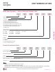
MULTI F MULTI F MAX MULTI F OUTDOOR UNIT Multi F and Multi F MAX Heat Pump System Engineering Manual General Data Table 1: 0XOWL ) 2XWGRRU 8QLW 6SHFL¿FDWLRQV LMU18CHV LMU24CHV LMU30CHV LMU36CHV Model Number 1 8,400~17,000~19,000 8,400~20,000~25,000 8,400~30,000~36,000 8,400~32,000~38,400 Cooling Capacity (Btu/h) (Min.~Rated~ Max.) 10,248~22,000~24,000 9,240~24,000~28,800 9,240~32,000~38,400 9,240~36,000~41,600 Heating Capacity (Btu/h)1 (Min.~Rated~ Max.
MULTI F MULTI F MAX MULTI F OUTDOOR UNIT General Data Table 2: /08 &+9 (I¿FLHQF\ 5DWLQJV 1,2 System Combined With LMU18CHV Non-Ducted Indoor Units Ducted Indoor Units Mixed Non-Ducted and Ducted Indoor Units Rated Cooling Capacity (Btu/h) EER (95°F) HSPF Low Heating Capacity (Btu/h) COP (17°F) 17,000 13.0 22.0 22,000 3.2 9.7 13,500 2.4 14,000 10.7 17.2 19,800 2.9 9.7 13,000 2.4 15,500 11.8 19.6 20,900 3.0 9.7 13,250 2.
MULTI F OUTDOOR UNIT 'LPHQVLRQV MULTI F MULTI F MAX Figure 6: LMU18CHV External Dimensions. [Unit : mm(inch)] Multi F and Multi F MAX Heat Pump System Engineering Manual Gravity point No. 12 | Part Name 1. Unit should be installed in compliance with the installation manual in the product box. 1 Air discharge grille 2 Gas pipe connection 3 Liquid pipe connection 4 Power & transmission connection 5 Main service valve(Gas) 6 Main service valve(Liquid) MULTI F OUTDOOR UNIT Note 2.
MULTI F MULTI F MAX MULTI F OUTDOOR UNIT 'LPHQVLRQV Figure 7: LMU24CHV External Dimensions. [Unit : mm(inch)] Gravity point Multi F Outdoor Unit Data No. Note Part Name 1. Unit should be installed in compliance with the installation manual in the product box. 1 Air discharge grille 2 Gas pipe connection 3 Liquid pipe connection 4 Power & transmission connection 5 Main service valve(Gas) 6 Main service valve(Liquid) 2.
MULTI F OUTDOOR UNIT 'LPHQVLRQV MULTI F MULTI F MAX Figure 8: LMU30CHV and LMU36CHV External Dimensions. [Unit : mm(inch)] Multi F and Multi F MAX Heat Pump System Engineering Manual Gravity point Note No. 14 | Part Name 1 Air discharge grille 2 Gas pipe connection 3 Liquid pipe connection 4 Main service valve(Liquid) 5 Main service valve(Gas) MULTI F OUTDOOR UNIT 1. Unit should be installed in compliance with the installation manual in the product box. 2.
MULTI F MULTI F MAX MULTI F OUTDOOR UNIT (OHFWULFDO DQG $FRXVWLF 'DWD Electrical Data Table 6: Electrical Data. Nominal Tons Unit Model No. 1.5 2 2.5 3 LMU18CHV LMU24CHV LMU30CHV LMU36CHV Hertz 60 Voltage Voltage Range MCA MOP Compressor Quantity (Min. to Max.) 208 - 230 13.3 14.3 16.6 17.9 187 - 253 20 20 25 25 1 1 1 1 8.9 9.4 10.8 11.2 Maximum Overcurrent Protection (MOP) is calculated as follows: (Largest motor FLA x 2.
MULTI F MULTI F MAX MULTI F OUTDOOR UNIT 5HIULJHUDQW )ORZ 'LDJUDP Figure 11: LMU18CHV Refrigerant Flow Diagram.
MULTI F MULTI F MAX MULTI F OUTDOOR UNIT 5HIULJHUDQW )ORZ 'LDJUDP Figure 12: LMU24CHV Refrigerant Flow Diagram.
MULTI F MULTI F MAX MULTI F OUTDOOR UNIT 5HIULJHUDQW )ORZ 'LDJUDP Figure 13: LMU30CHV and LMU36CHV Refrigerant Flow Diagram.
MULTI F MULTI F MAX MULTI F OUTDOOR UNIT Wiring Diagram Figure 14: LMU18CHV Wiring Diagram. Multi F Outdoor Unit Data 'XH WR RXU SROLF\ RI FRQWLQXRXV SURGXFW LQQRYDWLRQ VRPH VSHFL¿FDWLRQV PD\ FKDQJH ZLWKRXW QRWL¿FDWLRQ ©/* (OHFWURQLFV 8 6 $ ,QF (QJOHZRRG &OLIIV 1- $OO ULJKWV UHVHUYHG ³/*´ LV D UHJLVWHUHG WUDGHPDUN RI /* &RUS MULTI F OUTDOOR UNIT | 19
MULTI F OUTDOOR UNIT Wiring Diagram Multi F and Multi F MAX Heat Pump System Engineering Manual Figure 15: LMU24CHV Wiring Diagram. 20 | MULTI F OUTDOOR UNIT 'XH WR RXU SROLF\ RI FRQWLQXRXV SURGXFW LQQRYDWLRQ VRPH VSHFL¿FDWLRQV PD\ FKDQJH ZLWKRXW QRWL¿FDWLRQ ©/* (OHFWURQLFV 8 6 $ ,QF (QJOHZRRG &OLIIV 1- $OO ULJKWV UHVHUYHG ³/*´ LV D UHJLVWHUHG WUDGHPDUN RI /* &RUS MULTI F MULTI F MAX
MULTI F MULTI F MAX MULTI F OUTDOOR UNIT Wiring Diagram Figure 16: LMU30CHV and LMU36CHV Wiring Diagram. Multi F Outdoor Unit Data 'XH WR RXU SROLF\ RI FRQWLQXRXV SURGXFW LQQRYDWLRQ VRPH VSHFL¿FDWLRQV PD\ FKDQJH ZLWKRXW QRWL¿FDWLRQ ©/* (OHFWURQLFV 8 6 $ ,QF (QJOHZRRG &OLIIV 1- $OO ULJKWV UHVHUYHG ³/*´ LV D UHJLVWHUHG WUDGHPDUN RI /* &RUS MULTI F OUTDOOR UNIT | 21
MULTI F MULTI F MAX MULTI F OUTDOOR UNIT 2SHUDWLRQ 5DQJH Figure 17: Cooling and Heating Operation Ranges. Cooling 122 118 104 95 Outdoor Temperature (°F DB) 86 Heating 77 77 59 50 41 32 23 14 50 41 32 23 Continuous Operation 14 5 0 -4 5 -4 41 68 64 59 Warming up Operation Continuous Operation 68 Outdoor Temperature (°F WB) Multi F and Multi F MAX Heat Pump System Engineering Manual 113 50 57 59 68 Indoor Temperature (°F WB) 77 82.
MULTI F MAX OUTDOOR UNIT DATA “Product Features and Benefits” on page 24 “Mechanical Specifications” on page 25 “General Data” on page 26 “Dimensions” on page 28 “Electrical Data” on page 29 “Acoustic Data” on page 29 “Refrigerant Flow Diagrams” on page 30 “Wiring Diagrams” on page 31 “Operation Range” on page 33
MULTI F MULTI F MAX MULTI F MAX OUTDOOR UNIT )HDWXUHV DQG %HQH¿WV Multi F and Multi F MAX Heat Pump System Engineering Manual Multi F MAX inverter-driven heat pump systems can operate up to eight indoor units, providing cooling or heating for an entire home and zoning capabilities. Compact refrigerant pipes work in tandem with wiring to link the outdoor unit with all indoor units through a single or pair of branch distribution (BD) unit(s).
MULTI F MULTI F MAX MULTI F MAX SYSTEMS 0HFKDQLFDO 6SHFL¿FDWLRQV Multi F MAX Heat Pump Condensing Units Figure 19: Multi F MAX LMU480HV, LMU540HV, LMU600HV Outdoor Units. General Compressor The heat pump outdoor units are capable of operating in cooling mode from 14°F to 118°F ambient dry bulb (installing an optional Low Ambient Wind Baffle Kit will allow operation down to -4°F in cooling mode for Multi F MAX systems).
MULTI F MAX OUTDOOR UNIT Multi F and Multi F MAX Heat Pump System Engineering Manual General Data MULTI F MULTI F MAX Table 11: Multi F MAX Outdoor Unit General Data.
MULTI F MULTI F MAX MULTI F MAX OUTDOOR UNIT General Data Table 12: /08 +9 (I¿FLHQF\ 5DWLQJV 1,2 System Combined With LMU480HV Non-Ducted Indoor Units Ducted Indoor Units Mixed Non-Ducted and Ducted Indoor Units Rated Cooling EER Rated Heating COP Low Heating COP Energy Capacity (Btu/h) (95°F) SEER Capacity (Btu/h) (47°F) HSPF Capacity (Btu/h) (17°F) Star 48,000 12.5 19.35 54,000 3.7 10.0 34,080 3.3 Yes 44,000 10.8 17.5 50,000 3.3 9.7 32,720 3.0 No 46,000 11.6 18.5 52,000 3.
MULTI F MULTI F MAX MULTI F MAX OUTDOOR UNIT 'LPHQVLRQV Figure 20: LMU480HV, LMU540HV, and LMU600HV External Dimensions. 6-5/8 13 14-3/16 15-3/4 No. 6-1/2 6-1/2 24-13/32 Part Name 1 Liquid pipe connection 2 Gas pipe connection 3 Air discharge grille 4 Power & transmission connection 4 14-1/20 37-13/32 28 | MULTI F MAX OUTDOOR UNIT 'XH WR RXU SROLF\ RI FRQWLQXRXV SURGXFW LQQRYDWLRQ VRPH VSHFL¿FDWLRQV PD\ FKDQJH ZLWKRXW QRWL¿FDWLRQ ©/* (OHFWURQLFV 8 6 $ ,QF (QJOHZRRG &OLIIV 1-
MULTI F MULTI F MAX MULTI F MAX OUTDOOR UNIT (OHFWULFDO DQG $FRXVWLF 'DWD Electrical Data Table 15: LMU480HV, LMU540HV, and LMU600HV Electrical Data. Nominal Tons Unit Model No. Hertz 4.0 4.5 5.0 LMU480HV LMU540HV LMU600HV 60 60 60 Range Voltage Voltage (Min. to Max.) MCA 208 - 230 208 - 230 208 - 230 187 - 253 187 - 253 187 - 253 27.3 29.4 32.2 MOP Compressor Quantity Compressor Motor RLA 40 40 45 1 1 1 17.5 18.5 20.
MULTI F MULTI F MAX MULTI F MAX OUTDOOR UNIT 5HIULJHUDQW )ORZ 'LDJUDP Figure 23: LMU480HV, LMU540HV, and LMU600HV Refrigerant Flow Diagram.
MULTI F MULTI F MAX MULTI F OUTDOOR UNIT Wiring Diagram Figure 24: LMU480HV and LMU540HV Wiring Diagram. Multi F MAX Outdoor Unit Data 'XH WR RXU SROLF\ RI FRQWLQXRXV SURGXFW LQQRYDWLRQ VRPH VSHFL¿FDWLRQV PD\ FKDQJH ZLWKRXW QRWL¿FDWLRQ ©/* (OHFWURQLFV 8 6 $ ,QF (QJOHZRRG &OLIIV 1- $OO ULJKWV UHVHUYHG ³/*´ LV D UHJLVWHUHG WUDGHPDUN RI /* &RUS MULTI F MAX OUTDOOR UNIT | 31
MULTI F OUTDOOR UNIT Wiring Diagram Multi F and Multi F MAX Heat Pump System Engineering Manual Figure 25: LMU600HV Wiring Diagram. 32 | MULTI F MAX OUTDOOR UNIT 'XH WR RXU SROLF\ RI FRQWLQXRXV SURGXFW LQQRYDWLRQ VRPH VSHFL¿FDWLRQV PD\ FKDQJH ZLWKRXW QRWL¿FDWLRQ ©/* (OHFWURQLFV 8 6 $ ,QF (QJOHZRRG &OLIIV 1- $OO ULJKWV UHVHUYHG ³/*´ LV D UHJLVWHUHG WUDGHPDUN RI /* &RUS MULTI F MULTI F MAX
MULTI F MULTI F MAX MULTI F MAX OUTDOOR UNIT 2SHUDWLRQ 5DQJHV Figure 26: LMU480HV, LMU540HV, and LMU600HV Cooling and Heating Operation Ranges. Cooling 122 118 113 95 86 Heating 77 77 59 50 41 32 23 14 50 41 32 23 Continuous Operation 14 5 0 -4 5 -4 41 68 64 59 Warming up Operation Outdoor Temperature (°F WB) Continuous 68 50 57 59 68 73 77 Indoor Temperature (°F WB) 82.4 -13 50 59 68 77 81 86 91.
Multi F and Multi F MAX Heat Pump System Engineering Manual MULTI F MULTI F MAX 34 | MULTI F MAX OUTDOOR UNIT 'XH WR RXU SROLF\ RI FRQWLQXRXV SURGXFW LQQRYDWLRQ VRPH VSHFL¿FDWLRQV PD\ FKDQJH ZLWKRXW QRWL¿FDWLRQ ©/* (OHFWURQLFV 8 6 $ ,QF (QJOHZRRG &OLIIV 1- $OO ULJKWV UHVHUYHG ³/*´ LV D UHJLVWHUHG WUDGHPDUN RI /* &RUS
MULTI F MAX BD UNIT DATA “Features and Benefits” on page 36 “Mechanical Specifications” on page 37 “General Data” on page 38 “Dimensions” on page 39 “Refrigerant Flow Diagram” on page 40 “Wiring Diagram” on page 41 “Y-Branch Accessory” on page 42 “Branch Distribution Unit Orientation” on page 43
MULTI F MAX BD UNIT )HDWXUHV DQG %HQH¿WV MULTI F MULTI F MAX Multi F and Multi F MAX Heat Pump System Engineering Manual The Branch Distribution (BD) unit is a required accessory of Multi F MAX inverter-driven heat pump systems. Choose from two (2) port, three (3) port, or four (4) port BD units. Two (2) refrigerant pipes-one (1) liquid line and one (1) vapor line-run from the outdoor unit to the BD unit that is installed inside of a building.
MULTI F MULTI F MAX MULTI F MAX BD UNIT 0HFKDQLFDO 6SHFL¿FDWLRQV Branch Distribution Unit Figure 28:PMBD3620 Two-Port Branch Distribution Unit. General Branch distribution units are designed for use with LG Multi F MAX (LMU480HV and LMU540HV) outdoor units, and are internally piped, wired, assembled and run-tested at the factory.
MULTI F MULTI F MAX MULTI F MAX BD UNIT General Data Table 18: Multi F MAX BD Unit General Data. Model Number No. of Connectable Indoor Units1 PMBD3620 PMBD3630 PMBD3640 PMBD3641 1-2 1-3 1-4 24,000 24,000 24,000 48,000 0 ~ 122 72,000 0 ~ 122 73,000 0 ~ 122 1-4 24,000 for A,B,C Ports; 36,000 for D Port 73,000 0 ~ 122 R410A R410A R410A R410A 208-230, 1, 60 16 0.08 17-3/32 x 6-13/32 x 10-23/32 13 15 208-230, 1, 60 24 0.12 17-3/32 x 6-13/32 x 10-23/32 14.3 17 208-230, 1, 60 32 0.
MULTI F MULTI F MAX MULTI F MAX BD UNIT 'LPHQVLRQV Figure 31:PMBD3620, PMBD3630, PMBD3640, and PMBD3641 External Dimensions. Branch Distribution (BD) Unit Data 'XH WR RXU SROLF\ RI FRQWLQXRXV SURGXFW LQQRYDWLRQ VRPH VSHFL¿FDWLRQV PD\ FKDQJH ZLWKRXW QRWL¿FDWLRQ ©/* (OHFWURQLFV 8 6 $ ,QF (QJOHZRRG &OLIIV 1- $OO ULJKWV UHVHUYHG ³/*´ LV D UHJLVWHUHG WUDGHPDUN RI /* &RUS BD UNIT | 39
MULTI F MULTI F MAX MULTI F MAX BD UNIT 5HIULJHUDQW )ORZ 'LDJUDP Multi F and Multi F MAX Heat Pump System Engineering Manual Figure 32:PMBD3620, PMBD3630, PMBD3640, PMBD3641 Refrigerant Flow Diagram.
MULTI F MULTI F MAX MULTI F MAX BD UNIT Wiring Diagram Figure 33:PMBD3620, PMBD3630, PMBD3640, PMBD3641 Wiring Diagram. Model Dependant Model Dependant Branch Distribution (BD) Unit Data Model Dependant Troubleshooting Model Dependant PMBD3620 BD Unit supplied with "A, B". PMBD3630 BD Unit supplied with "A, B, C". PMBD3640 and PMBD3641 BD Units supplied with "A, B, C, D". 'XH WR RXU SROLF\ RI FRQWLQXRXV SURGXFW LQQRYDWLRQ VRPH VSHFL¿FDWLRQV PD\ FKDQJH ZLWKRXW QRWL¿FDWLRQ ©/* (OHFWURQLFV 8 6 $
MULTI F MULTI F MAX MULTI F MAX BD UNIT 0XOWL ) 0$; < %UDQFK $FFHVVRU\ Y-Branch accessory PMBL5620 is required when installing two branch distribution units in parallel on one Multi F MAX system. Table 19: 0XOWL ) 0$; < %UDQFK 6SHFL¿FDWLRQV Multi F and Multi F MAX Heat Pump System Engineering Manual Model PMBL5620 3RUW ,GHQWL¿HU LQFK Y-Branch Type 1 2 3 Liquid Ø3/8 Ø3/8 Ø3/8 Vapor Ø3/4 Ø3/4 Ø3/4 Dimensions (inch) Y-Branch Type X Y Liquid 13.80 3.24 Vapor 12.48 3.
MULTI F MULTI F MAX MULTI F MAX BD UNIT %UDQFK 'LVWULEXWLRQ 8QLW 2ULHQWDWLRQ Multi F MAX Branch Distribution (BD) Units can be installed in a multitude of options to fit various building configurations and job or application requirements. Multi F MAX BD Units include electronic expansion valves that properly seat only if the BD Unit is installed in an acceptable orientation.
Multi F and Multi F MAX Heat Pump System Engineering Manual MULTI F MULTI F MAX 44 | BD UNIT 'XH WR RXU SROLF\ RI FRQWLQXRXV SURGXFW LQQRYDWLRQ VRPH VSHFL¿FDWLRQV PD\ FKDQJH ZLWKRXW QRWL¿FDWLRQ ©/* (OHFWURQLFV 8 6 $ ,QF (QJOHZRRG &OLIIV 1- $OO ULJKWV UHVHUYHG ³/*´ LV D UHJLVWHUHG WUDGHPDUN RI /* &RUS
APPLICATION GUIDELINES “Equipment Selection Procedure” on page 46 “Building Ventilation Design Guide” on page 52 “Placement Considerations” on page 57
Multi F and Multi F MAX Indoor Unit Engineering Manual EQUIPMENT SELECTION PROCEDURE MULTI F MULTI F MAX To choose the multi-zone system that is the most appropriate for the space, as with traditional air-conditioning systems, follow similar protocols outlined in Manual J from the Air Conditioning Contractors of America (ACCA; see www.acca.org). 1. Obtain the design conditions, and calculate the maximum cool and heat loads for the structure. 2.
MULTI F MULTI F MAX EQUIPMENT SELECTION PROCEDURE Multiplier Examples Example 1 Branch Distribution Unit (PMBD3641) Outdoor Unit: LMU540HV First Indoor Unit: + Second Indoor Unit: + Third Indoor Unit: LMCN125HV LSN090HSV4 LMVN360HV Total Capacity Index = 12 + 9 Branch Distribution Unit (PMBD3620) Example 2 + 36 x 1.3 Table 20: Allowable Indoor Unit to Outdoor Unit Connections. Indoor units Outdoor Unit: LMU540HV Total Capacity Index = = 67.
MULTI F MULTI F MAX EQUIPMENT SELECTION PROCEDURE Table 21: Rated Outdoor Unit Capacity. Outdoor Units LMU18CHV LMU24CHV LMU30CHV LMU36CHV LMU480HV LMU540HV LMU600HV Multi F and Multi F MAX Indoor Unit Engineering Manual Rated Capacity (Btu/h)* Connectable Indoor Units Cooling Heating Minimum No. of Connectable IDUs Maximum No.
MULTI F MULTI F MAX EQUIPMENT SELECTION PROCEDURE Using the System Combination Tables Multi F system combination tables illustrate how each indoor unit receives a percentage of total outdoor unit rated capacity.
MULTI F MULTI F MAX EQUIPMENT SELECTION PROCEDURE Table 23: Multi F MAX Outdoor Unit to Branch Distribution Unit Refrigerant Line Length Derates. Main Piping Length (feet) 16.4 32.8 49.2 65.6 82.0 98.4 114.8 131.2 147.6 164.0 180.4 Cooling Capacity (%) 100.0 98.8 97.3 95.8 94.3 92.8 91.3 89.8 88.3 86.8 85.3 Heating Capacity (%) 100.0 99.6 99.2 98.7 98.3 97.8 97.4 96.9 96.5 96.0 95.
MULTI F MULTI F MAX EQUIPMENT SELECTION PROCEDURE Altitude Correction Factor The impact of air density must be considered on systems installed at a significant altitude above sea level, therefore, locally accepted altitude correction factors must be applied. Defrost Correction Factor for Heating Operation The outdoor unit heating capacity may need to be adjusted for frost accumulation on air-cooled systems.
BUILDING VENTILATION DESIGN GUIDE MULTI F MULTI F MAX Multi F and Multi F MAX Indoor Unit Engineering Manual ASHRAE Standards 62.1 and 62.2 (depending on if the building is residential or commercial), and local codes specify the minimum volume of airflow that must be provided to an occupied space. Outdoor air is required to minimize adverse health effects, and it provides acceptable indoor air quality for building occupants.
MULTI F MULTI F MAX BUILDING VENTILATION DESIGN GUIDE Method 2: Unconditioned Outdoor Air (Non-Ducted, Fan Assisted Ventilation) When approved by local codes, the fan assisted ventilation method uses exhaust fans to remove air from the building, and outdoor air is drawn into occupied spaces through a wall louver or gravity roof intake hood.
BUILDING VENTILATION DESIGN GUIDE MULTI F MULTI F MAX Method 3: Unconditioned Outdoor Air Ducted to Indoor Units Multi F and Multi F MAX Indoor Unit Engineering Manual Untreated outdoor air is channeled through a duct system that is piped to the return air duct on Multi F ducted indoor units or to the frame of Multi F four-way cassettes. 2XWVLGH DLU PD\ ÀRZ EDFNZDUG WKURXJK WKH UHWXUQ DLU ¿OWHU JULOOH ZKHQ WKH LQGRRU XQLW IDQ VSHHG VORZV RU VWRSV LQ UHVSRQVH WR FKDQJHV LQ WKH VSDFH ORDG 7KLV PD\ UHVX
MULTI F MULTI F MAX BUILDING VENTILATION DESIGN GUIDE Method 4: Coupled Dedicated Outdoor Air (CDOA) A separate, dedicated outdoor air system delivers air directly to a Multi F indoor unit or to the return air duct system. After mixing with the return air stream, ventilation air passes through the indoor unit and into the conditioned space. The pretreatment system is capable of filtering, conditioning, and dehumidifying outdoor air to room neutral conditions. 2XWVLGH DLU PD\ ÀRZ EDFNZDUG WKURXJK WKH UHWX
BUILDING VENTILATION DESIGN GUIDE MULTI F MULTI F MAX Method 5: Decoupled Dedicated Outdoor Air System (DDOAS) LG recommends using the DDOAS method in all installations. Advantages Disadvantages • May be used with the full lineup of Multi F indoor units. • The outdoor air unit may supply “neutral” air to the occupant space even when the Multi F indoor unit fan changes speed or cycles on and off. DDOAS controls do not have to be interlocked with the Multi V F system.
MULTI F MULTI F MAX PLACEMENT CONSIDERATIONS Selecting the Best Location for the Indoor Units Select a location for installing the indoor units that will meet the following conditions: • Within allowable parameters for proper connection to the outdoor unit (or Branch Distribution unit, if a Multi F MAX system). • So that condensation drainage can be conveniently routed away. • Include enough space around the indoor unit so that it is accessible for maintenance and service purposes.
MULTI F MULTI F MAX PLACEMENT CONSIDERATIONS Multi F and Multi F MAX Indoor Unit Engineering Manual Selecting the Best Location for the Outdoor Unit, continued. • Where it will not be subjected to direct thermal radiation from other heat sources, nor an area that would not expose the outdoor unit to heat or steam like discharge from boiler stacks, chimneys, steam relief ports, other air conditioning units, kitchen vents, plumbing vents, and other sources of extreme temperatures.
MULTI F MULTI F MAX PLACEMENT CONSIDERATIONS Outdoor Unit Platform Requirements Figure 45: Outdoor Unit Foundation Requirements.
MULTI F MULTI F MAX PLACEMENT CONSIDERATIONS Multi F and Multi F MAX Indoor Unit Engineering Manual Tie-Downs and Lightening Protection Figure 48: Lightening Protection Diagram. Tie-Downs • The strength of the roof must be checked before installing the outdoor units. • If the installation site is prone to high winds or earthquakes, when installing on the wall or roof, securely anchor the mounting base using a field-provided tie-down configuration approved by a local professional engineer.
MULTI F MULTI F MAX PLACEMENT CONSIDERATIONS Clearance Requirements when Different Obstacles are Present (Unit: Inch). Obstacle on the suction side only. Obstacles on the suction side and on both left and right sides. Min M um inim 12" imu m1 2" imu m2 im Min 4" um 12" Application Guidelines Min 0" m2 imu Min imu m2 0" Minimum 40" Max Minimum 40" Obstacles above and on the air intake side.
MULTI F MULTI F MAX PLACEMENT CONSIDERATIONS Clearance Requirements when Different Obstacles are Present, continued. (Unit: Inch) Where there are obstacles on both suction and discharge sides (discharge side obstacle is higher than the outdoor unit). Where there are obstacles above, and on both suction and discharge sides (discharge side obstacle is higher than the outdoor unit). imu m2 0" Table 28: Ratio among H, A, and L.
MULTI F MULTI F MAX PLACEMENT CONSIDERATIONS Installing Outdoor Units Indoors LG Multi F / Multi F MAX outdoor units are engineered to be mounted outdoors and include technology designed to minimize the negative effects of winter weather’s freezing rain, sleet, and snow. Some building projects, however, necessitate placing the HVAC outdoor units indoors: • Lack of ground space. • Lack of an appropriate outdoor location that meets system design requirements.
MULTI F MULTI F MAX PLACEMENT CONSIDERATIONS Provide a means to drain the condensate generated during heating mode and defrost cycle in addition to rainwater that infiltrates the inlet louver enclosed area. • Install a field-provided drain pan under the outdoor units and provide a path to a nearby floor drain.
MULTI F MULTI F MAX PLACEMENT CONSIDERATIONS Open Rate by Louver Radian Figure 52: Open Rate by Louver Radian Formula. W h ho H Application Guidelines ho = h * COS Total Area (A) = H * W Number of Open Spaces (N) = (Number of Louvers - 1) Effective Area (Af) = ho * W * N Louver Open Rate (n) = Af / A Af = A * n Side View Effective Cross Section Area Front View Confirming Air Flow Rate / Total Opening Rate Figure 51: Example of Installing Outdoor Unit Indoors.
Multi F and Multi F MAX Indoor Unit Engineering Manual MULTI F MULTI F MAX 66 | APPLICATION GUIDELINES 'XH WR RXU SROLF\ RI FRQWLQXRXV SURGXFW LQQRYDWLRQ VRPH VSHFL¿FDWLRQV PD\ FKDQJH ZLWKRXW QRWL¿FDWLRQ ©/* (OHFWURQLFV 8 6 $ ,QF (QJOHZRRG &OLIIV 1- $OO ULJKWV UHVHUYHG ³/*´ LV D UHJLVWHUHG WUDGHPDUN RI /* &RUS
REFRIGERANT PIPING DESIGN & LAYOUT BEST PRACTICES “Design Guideline Summary” on page 68 “Creating a Balanced / Quality Piping System” on page 70 “Manual Layout Procedure” on page 70 “LG Engineered Multi F MAX Y-Branch Kits” on page 71 “Refrigerant Charge” on page 72 “Selecting Field-Supplied Copper Tubing” on page 74 “Refrigerant Piping System Layout” on page 76 “Piping Insulation” on page 84 “Condensate Drain Piping” on page 85 “Cut Sheet” on page 87
MULTI F MULTI F MAX REFRIGERANT PIPING DESIGN Design Guideline Summary The following are examples of manual pipe size calculations. Designers are highly encouraged to use LATS for Multi F systems. Device Connection Limitations • The minimum number of connected and operating indoor units to Multi F / Multi F MAX systems is two, taking into consideration the minimum combination ratio.
MULTI F MULTI F MAX REFRIGERANT PIPING DESIGN Design Guideline Summary The following are examples of manual pipe size calculations. Designers are highly encouraged to use LATS for Multi F systems. Multi F MAX System with One Branch Distribution Unit Example: LMU540HV outdoor unit with four (4) indoor units, and one (1) branch distribution unit connected. IDU BDU A B h2 ≤ 49.2 feet IDU B IDU h1 ≤ 98.4 feet B h3 ≤ 32.8 feet Refrigerant Piping Design and Best Practices ODU: Outdoor Unit.
REFRIGERANT PIPING DESIGN Creating a Balanced System / Manual Layout Procedure MULTI F MULTI F MAX Creating a Balanced / Quality Piping System Multi F and Multi F MAX Indoor Unit Engineering Manual Unlike designing duct-work or chilled and hot water pipe systems where balancing dampers, ball valves, orifices, circuit setters, or other flow control devices can be installed to modify or balance the flow of cooling medium, these cannot be used in a Multi F system.
MULTI F MULTI F MAX REFRIGERANT PIPING DESIGN LG Engineered Multi F MAX Y-Branch Kit Multi F MAX Y-Branch Kit PMBL5620 Figure 53: Y-Branch Connections. The LG supplied Y-Branch Kit PMBL5620 MUST be used when two branch distribution units are connected on one Multi F MAX system. Field-supplied fittings are not permitted. Each Y-Branch kit comes with two (2) Y-branches (one for the liquid line and one for the vapor line) and insulation covers.
MULTI F MULTI F MAX REFRIGERANT PIPING DESIGN Refrigerant Charge Multi F and Multi F MAX Indoor Unit Engineering Manual LG Multi F and Multi F MAX outdoor units ship from the factory with a charge of R410A refrigerant. A trim charge may need to be added to take into account additional piping length. To determine the additional refrigerant that is needed, apply the formulas below, and record the results.
MULTI F MULTI F MAX REFRIGERANT PIPING DESIGN Refrigerant Charge Multi F MAX Systems $GGLWLRQDO FKDUJH OEV 7RWDO 0DLQ 3LSLQJ /HQJWK >$@ &KDUJHOHVV 3LSH /HQJWK RI 0DLQ 3LSH >/@ [ D ,QVWDOOHG /HQJWK RI %UDQFK >% @ ± &KDUJHOHVV 3LSH /HQJWK >%@ [ E ,QVWDOOHG /HQJWK RI %UDQFK >% @ ± &KDUJHOHVV 3LSH /HQJWK >%@ [ E ,QVWDOOHG /HQJWK RI %UDQFK >% @ ± &KDUJHOHVV 3LSH /HQJWK >%@ [ E - CF (Correction Factor) x 3.
MULTI F MULTI F MAX REFRIGERANT PIPING DESIGN Selecting Field-Supplied Copper Tubing Multi F and Multi F MAX Indoor Unit Engineering Manual Type ACR copper is the only approved refrigerant pipe material for use with LG Multi F air conditioning products. ACR rated tubing is the only type that ships with yellow caps. Approved tubing for use with Multi V products will be marked “R410 RATED” along the length of the tube.
MULTI F MULTI F MAX INSTALLATION & LAYOUT BEST PRACTICES Selecting Field-Supplied Copper Tubing Table 39: Linear Thermal Expansion of Copper Tubing in Inches. 1 35° 40° 45° 50° 55° 60° 65° 70° Fluid Temperature °F 75° 80° 85° 90° 95° 100° 105° 110° 115° 120° 125° 130° 0.04 0.08 0.12 0.16 0.20 0.24 0.28 0.32 0.36 0.40 0.48 0.56 0.64 0.72 0.04 0.08 0.12 0.16 0.20 0.24 0.28 0.32 0.36 0.40 0.48 0.56 0.64 0.72 0.05 0.10 0.15 0.20 0.25 0.30 0.35 0.40 0.45 0.50 0.60 0.70 0.80 0.90 0.06 0.12 0.
INSTALLATION & LAYOUT BEST PRACTICES Refrigerant Piping System Layout MULTI F MULTI F MAX Multi F and Multi F MAX Indoor Unit Engineering Manual Field-Provided Isolation Ball Valves LG recommends installing field-supplied ball valves with Schrader ports at each indoor unit. Full-port isolation ball valves with Schrader ports (positioned between valve and indoor unit) rated for use with R410A refrigerant should be used on both the liquid and vapor lines.
MULTI F MULTI F MAX INSTALLATION & LAYOUT BEST PRACTICES Refrigerant Piping System Layout Figure 62: Installing an Insert Into a Concrete Beam. Inserts and Pipe Supports Inserts An insert can be installed into a floor or beam before the concrete sets so that fittings such as ducts, pipes, or suspension bolts can be added at a later time. Decide where the inserts should be placed before support installation.
INSTALLATION & LAYOUT BEST PRACTICES Refrigerant Piping System Layout MULTI F MULTI F MAX Examples of Supports Figure 67: U-Bolt Support with Insulation. Figure 68: O-Ring Support with Insulation. Figure 69: Saddle-Type Support. Bolt Support at Intervals Between 5 and 6-3/4 Feet Insulation Multi F and Multi F MAX Indoor Unit Engineering Manual Bolt 1.5t Plate PVC PVC Do not compress the insulation with the saddle-type support.
MULTI F MULTI F MAX INSTALLATION & LAYOUT BEST PRACTICES Refrigerant Piping System Layout Pipe Sleeves at Penetrations LG requires that all pipe penetrations through walls, floors, and pipes buried underground be routed through a properly insulated sleeve that is sufficiently sized to provide free movement of the pipe and does not compress the insulation. Underground refrigerant pipe shall be routed inside a protective sleeve to prevent insulation deterioration.
INSTALLATION & LAYOUT BEST PRACTICES Refrigerant Piping System Layout MULTI F MULTI F MAX Multi F Outdoor Unit to Indoor Unit Piping Connections Figure 77: Multi F Refrigerant Pipe Connections (LMU36CHV shown as example). Multi F and Multi F MAX Indoor Unit Engineering Manual Avoid Pipe Damage • When routing field-provided piping, avoid damaging the outdoor unit from excessive vibration. • Properly insulate the liquid and gas lines separately up to the point of connection at the unit frame.
MULTI F MULTI F MAX INSTALLATION & LAYOUT BEST PRACTICES Refrigerant Piping System Layout Multi F MAX Outdoor Unit System Piping Connections Avoid Pipe Damage • When routing field-provided piping, avoid damaging the outdoor unit from excessive vibration. • Properly insulate the liquid and gas lines separately up to the point of connection at the unit frame. • See table below for Multi F MAX outdoor unit connection types. Table 46: Outdoor Unit Piping Connections.
INSTALLATION & LAYOUT BEST PRACTICES Refrigerant Piping System Layout MULTI F MULTI F MAX Multi F MAX Outdoor Unit System Piping Connections, continued. 1. Align the center of the piping sections and tighten the flare nut by hand. 2. Tighten the flare nut with a torque wrench, using the arrows on the wrench as a guide, until a click is heard. 3. Wrap insulation around the connection. Figure 82: Possible Outdoor Unit or Branch Distribution Unit to Indoor Unit Connections.
MULTI F MULTI F MAX INSTALLATION & LAYOUT BEST PRACTICES Refrigerant Piping System Layout Brazing Practices Keep the piping system free of contaminants and debris such as copper burrs, slag, or carbon dust during installation. 1. All joints are brazed in the field. Multi F refrigeration system components contain very small capillary tubes, small orifices, electronic expansion valves, oil separators, and heat exchangers that can easily become blocked.
INSTALLATION & LAYOUT BEST PRACTICES Piping Insulation MULTI F MULTI F MAX Multi F and Multi F MAX Indoor Unit Engineering Manual Refrigerant Piping System Insulation All refrigerant piping including Y-branch connections, field-provided isolation ball valves, service valves, and elbows shall be completely insulated using closed cell pipe insulation. To prevent heat loss/heat gain through the refrigerant piping, all refrigerant piping including liquid lines and vapor lines shall be insulated VHSDUDWHO\ ,
MULTI F MULTI F MAX INSTALLATION & LAYOUT BEST PRACTICES Condensate Drain Piping Condensate Drain Piping Outdoor Units Outdoor unit requires condensate drain piping. Condensate drain pipe is constructed with materials approved by local code. See pages 60 to 62 for information in reference to outdoor unit placement and condensate drainage.
INSTALLATION & LAYOUT BEST PRACTICES Condensate Drain Piping MULTI F MULTI F MAX Multi F and Multi F MAX Indoor Unit Engineering Manual Common Indoor Unit Drainage System It is usual work practice to connect individual indoor unit drain pipes to one common indoor unit drainage system. The diameter of the common vertical drain pipe should be as large as necessary. (For systems with <80,000 Btu/h total capacity of all connected indoor units, the standard size for the common vertical drain pipe is 0.
MULTI F MULTI F MAX CUT SHEET Y-Branch Kit • LG Y-Branch Kit PMBL5620 is required when installing two branch distribution units in parallel on one LG Multi F MAX system. • The kit must be properly installed following instructions in the applicable LG manual. Field-supplied branch fittings are not permitted. • Kit components must be kept free of debris and be dry before installation. • All Y-Branch Kits include a clam shell, peel-and-stick insulation jacket. Table 54: Fitting Properties.
Multi F and Multi F MAX Indoor Unit Engineering Manual MULTI F MULTI F MAX 88 | DESIGN & PRACTICES 'XH WR RXU SROLF\ RI FRQWLQXRXV SURGXFW LQQRYDWLRQ VRPH VSHFL¿FDWLRQV PD\ FKDQJH ZLWKRXW QRWL¿FDWLRQ ©/* (OHFWURQLFV 8 6 $ ,QF (QJOHZRRG &OLIIV 1- $OO ULJKWV UHVHUYHG ³/*´ LV D UHJLVWHUHG WUDGHPDUN RI /* &RUS
WIRING CONNECTIONS “General Information” on page 90 “Power Wiring (208-230V) and Communications Cable Details” on page 91 “Indoor Unit Group Control” on page 99
WIRING CONNECTIONS Multi F and Multi F MAX Indoor Unit Engineering Manual General Information MULTI F MULTI F MAX • All power (line voltage) wiring and communication cable installation must be performed by trained service providers working in accordance with local, state, and National Electrical Code (NEC) / UL / ETL federal regulations related to electrical equipment and wiring, and following the manufacturer product diagrams, requirements, and instructions in this manual.
MULTI F MULTI F MAX WIRING CONNECTIONS General Information General Communication Cable Specifications 6” ± 6/1 6” 2/1 Power Wiring, Ground to Outdoor Unit GN /YL 13/ 16” 6” ± 6/1 Power Wiring, Ground, Communication Cable From Outdoor Unit To Indoor Unit or from the Outdoor Unit to the Branch Distribution Unit GN/YL = (Ground, Yellow) 6” 2/1 GN /YL 13/ 16” Connecting the Power Wiring / Communications Cable Best practice dictates using ring or spade terminals to terminate power wiring at the
MULTI F MULTI F MAX WIRING CONNECTIONS General Information Figure 99: Multi F System General Power / Communications System Schematic. Indoor Units Multi F and Multi F MAX Indoor Unit Engineering Manual Power Supply Circuit Breaker Ground Wiring Outdoor Unit Figure 100: Multi F MAX System General Power / Communications System Schematic. Indoor Unit BD Unit Power Supply Circuit Breaker BD Unit Ground Wiring Outdoor Unit • Secure the separate wires in the control box panel using zip ties.
MULTI F MULTI F MAX WIRING CONNECTIONS Power Wiring (208-230V) and Communications Cable Details • Find the outdoor unit terminal block by unscrewing the control access panel. Figure 101: Example of Power Wiring and Communications Cable Terminations. Control Access Panel • Side panel of the outdoor unit has knockout holes for the conduits. After install is complete, seal up any gaps between the panel and the conduits.
MULTI F MULTI F MAX WIRING CONNECTIONS Power Wiring (208-230V) and Communications Cable Details Figure 102: Multi F LMU18CHV System Power Wiring and Communications Cable.
MULTI F MULTI F MAX WIRING CONNECTIONS Power Wiring (208-230V) and Communications Cable Details Figure 103: Multi F LMU24CHV System Power Wiring and Communications Cable.
MULTI F MULTI F MAX WIRING CONNECTIONS Power Wiring (208-230V) and Communications Cable Details Figure 104: Multi F LMU30CHV and LMU36CHV System Power Wiring and Communications Cable.
MULTI F MULTI F MAX WIRING CONNECTIONS Power Wiring (208-230V) and Communications Cable Details Figure 105: Multi F MAX LMU480HV and LMU540HV System Power Wiring and Communications Cable.
MULTI F MULTI F MAX WIRING CONNECTIONS Power Wiring (208-230V) and Communications Cable Details Figure 106: Multi F MAX LMU600HV System Power Wiring and Communications Cable.
MULTI F MULTI F MAX WIRING CONNECTIONS Indoor Unit Group Control Communication Cables Between Multiple Indoor Units Operating as a Group (Group Control) 1. If any indoor units were specified to operate in unison, use one (or multiple) three-core Group Control Kit (sold separately) containing extension and Y-splitter cables. One (1) group control cable kit for each indoor unit in the group except for the last indoor unit. Figure 107: Indoor Unit Group to Zone Controller Connections.
MULTI F MULTI F MAX ACRONYMS Multi F and Multi F MAX Indoor Unit Engineering Manual Table 58: Table of Acronyms.
20001747 ISO 9001: 2008 LG ELECTRONICS INC. LG Electronics, U.S.A., Inc. Commercial Air Conditioning Division 4300 North Point Parkway Alpharetta, Georgia 30022 www.lg-vrf.com LG Electronics Products Support 1-888-865-3026 USA Follow the prompts for HVAC products.