
Manual
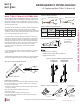
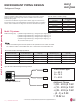
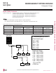
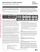
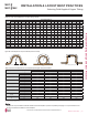
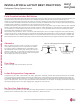
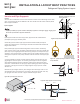
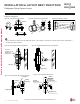
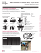
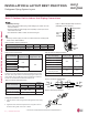

Table 42: Outdoor Unit Piping Connections.
Figure 77: Multi F Refrigerant Pipe Connections
(LMU36CHV shown as example).
Avoid Pipe Damage
• When routing field-provided piping, avoid damaging the outdoor unit from
excessive vibration.
• Properly insulate the liquid and gas lines separately up to the point of con-
nection at the unit frame.
• See table below for Multi F outdoor unit connection types.
Main gas
valve
Main liquid
valve
Gas Piping Connections
Liquid
Piping
Connections
A-UNIT
B-UNIT
C-UNIT
D-UNIT
Connection sockets (included as a factory-supplied accessory with
the indoor units) may need to be used when piping the indoor units
to the outdoor unit. If a 36K indoor unit is included, the connection
sockets are included with the Branch Distribution unit.
Indoor Unit Capacity
Vapor (in., OD)
Liquid (in.,
OD)
A B A B
18,000 Btu/h: Wall-Mounted ĺĺ ĺ
18,000 Btu/h: Low Static
Duct, Four-Way Cassette
ĺ N/A
24,000 Btu/h ĺ N/A
A
B
Flare
to
Indoor
Unit
Flare
to
Outdoor
Unit
1. Align the center of the piping sections and tighten the flare nut by
hand.
2. Tighten the flare nut with a torque wrench, using the arrows on
the wrench as a guide, until a click is heard.
INSTALLATION & LAYOUT BEST PRACTICES
Refrigerant Piping System Layout
Multi F Outdoor Unit to Indoor Unit Piping Connections
Outdoor Unit Piping Connections LMU18CHV LMU24CHV LMU30CHV LMU36CHV
Liquid Line Connection (in., OD) x Qty. 1/4 x 2 1/4 x 3 1/4 x 4 1/4 x 4
Vapor Line Connection (in., OD) x Qty. 3/8 x 2 3/8 x 3 3/8 x 4 3/8 x 4
Table 43: Indoor Unit Pipe Sizes.
Table 44: Connection Socket Dimensions.
Figure 78: Connection Socket Diagram.
Using the Connection Socket
Connection Socket
Figure 79: Performing Connections.
Indoor Unit Capacity
Vapor Line
Piping Size (in., OD)
Liquid Line
Piping Size (in., OD)
7,000 Btu/h
Ø3/8
Ø1/4
9,000 Btu/h
12,000 Btu/h
15,000 Btu/h
18,000 Btu/h
Ø1/2
24,000 Btu/h
Table 45: Indoor Unit Piping Connections.
Indoor Unit Capacity
Vapor Line
Conn. (in., OD)
Liquid Line
Conn. (in., OD)
7,000 Btu/h
Ø3/8 Ø1/4
9,000 Btu/h
12,000 Btu/h
15,000 Btu/h
18,000 Btu/h: Wall-Mounted Ø5/8 Ø3/8
18,000 Btu/h: Low Static Duct,
Four-Way Cassette
Ø1/2 Ø1/4
24,000 Btu/h Ø1/2 Ø1/4
• Correctly route the piping so it does not make contact with mounting bolts.
Allow room for field installation.
'XHWRRXUSROLF\RIFRQWLQXRXVSURGXFWLQQRYDWLRQVRPHVSHFL¿FDWLRQVPD\FKDQJHZLWKRXWQRWL¿FDWLRQ
©/*(OHFWURQLFV86$,QF(QJOHZRRG&OLIIV1-$OOULJKWVUHVHUYHG³/*´LVDUHJLVWHUHGWUDGHPDUNRI/*&RUS
80 | DESIGN & PRACTICES
Multi F and Multi F MAX Indoor Unit Engineering Manual
MULTI
F
MAX
MULTI
F