
Manual


INSTALLATION & LAYOUT BEST PRACTICES
Refrigerant Piping System Layout
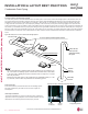
Multi F MAX Outdoor Unit System Piping Connections
Branch Distribution to Indoor Unit Piping Connections
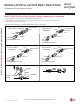
• Install indoor unit liquid and vapor refrigerant pipes (and connection wiring) to the appropriate branch distribution ports.
• Clearly note on the indoor unit’s refrigerant piping (liquid, vapor) which branch distribution port it is connected to (A, B, C, D).
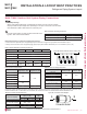
Outdoor Unit Piping Connections LMU480HV and LMU540HV
Liquid Line Connection (in., OD) x Qty. 3/8 x 1
Vapor Line Connection (in., OD) x Qty. 3/4 x 1
Avoid Pipe Damage
• When routing field-provided piping, avoid damaging the outdoor unit from excessive vibration.
• Properly insulate the liquid and gas lines separately up to the point of connection at the unit frame.
• See table below for Multi F MAX outdoor unit connection types.
Table 46: Outdoor Unit Piping Connections.
Table 47: Branch Distribution Unit Piping Connections.
Table 48: Indoor Unit Piping Connections.
Branch Distribution Unit PMBD3620 PMBD3630 PMBD3640 PMBD3641
Piping Connections to Outdoor Unit
Liquid (in., OD) x Qty. Ø3/8 x 1
Vapor (in., OD) x Qty. Ø3/4 x 1
Piping Connections to Indoor Units
Liquid (in., OD) x Qty. Ø1/4 x 2 Ø1/4 x 3 Ø1/4 x 4 Ø1/4 x 4
Vapor (in., OD) x Qty. Ø3/8 x 2 Ø3/8 x 3 Ø3/8 x 4 Ø3/8 x 3, Ø1/2 x 1
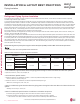
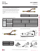
Table 49: Connection Socket Dimensions.
Connection sockets (included as a factory-supplied accessory with the indoor units) may need to be used when piping the indoor units to the
branch distribution unit. If a 36K indoor unit is included, the connection sockets are included with the Branch Distribution unit.
Indoor Unit Capacity
Vapor (in., OD)
Liquid (in.,
OD)
A B A B
18,000 Btu/h: Wall-Mounted ĺĺ ĺ
18,000 Btu/h: Low Static
Duct, Four-Way Cassette
ĺ N/A
24,000 Btu/h ĺ N/A
36,000 Btu/h ĺ ĺ
Connection Socket
A
B
Figure 80: Branch Distribution Ports to Indoor Units.
ABC D
Figure 81: Connection Socket Diagram.
Indoor Unit Capacity
Vapor Line
Piping Size (in., OD)
Liquid Line
Piping Size (in., OD)
7,000 Btu/h
Ø3/8
Ø1/4
9,000 Btu/h
12,000 Btu/h
15,000 Btu/h
18,000 Btu/h
Ø1/2
24,000 Btu/h
36,000 Btu/h Ø5/8 Ø3/8
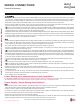
Table 50: Indoor Unit Pipe Sizes.
Indoor Unit Capacity
Vapor Line
Conn. (in., OD)
Liquid Line
Conn. (in., OD)
7,000 Btu/h
Ø3/8 Ø1/4
9,000 Btu/h
12,000 Btu/h
15,000 Btu/h
18,000 Btu/h: Wall-Mounted Ø5/8 Ø3/8
18,000 Btu/h: Low Static Duct,
Four-Way Cassette
Ø1/2 Ø1/4
24,000 Btu/h Ø1/2 Ø1/4
36,000 Btu/h Ø5/8 Ø3/8
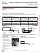
• Correctly route the piping so it does not make contact with mount-
ing bolts. Allow room for field installation.
'XHWRRXUSROLF\RIFRQWLQXRXVSURGXFWLQQRYDWLRQVRPHVSHFL¿FDWLRQVPD\FKDQJHZLWKRXWQRWL¿FDWLRQ
©/*(OHFWURQLFV86$,QF(QJOHZRRG&OLIIV1-$OOULJKWVUHVHUYHG³/*´LVDUHJLVWHUHGWUDGHPDUNRI/*&RUS
DESIGN & PRACTICES | 81
Refrigerant Piping Design and Best Practices
MULTI
F
MAX
MULTI
F