ENGLISH ESPAÑOL FRANÇAIS OWNER’S MANUAL AIR CONDITIONER Please read this manual carefully before operating your set and retain it for future reference. TYPE : Room Air Conditioner http://www.lghvac.com www.lg.
Packaged Terminal Air Conditioner/Heat Pump Owner's Manual TABLE OF CONTENTS Safety Precautions..........................3 FOR YOUR RECORDS Write the model and serial numbers here: Before Operation.............................7 Model # Serial # Introduction ....................................8 You can find them on a label on the side of each unit. Dealer's Name Electrical Safety ..............................
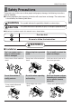
Safety Precautions Safety Precautions WARNING This symbol indicates the possibility of death or serious injury. CAUTION This symbol indicates the possibility of injury or damage to properties only. n Meanings of symbols used in this manual are as shown below. Don't do this! Be sure to follow the instruction. WARNING n Installation Donʼt use a power cord, a plug, or a loose socket which is damaged. • It may cause a fire or electrical shock. Always plug into a grounded outlet.
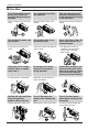
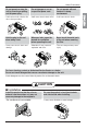
Safety Precautions n Operation Do not place objects on the power cord. Protect the cord from being pinched or damaged. • There is danger of fire or electric shock. Do not place the power cord near a heater. • It may cause fire and electric shock. Use a dedicated circuit for this appliance. • An overloaded circuit is a fire hazard. Do not allow water to run into electric parts. • It will cause failure of machine or electric shock.
Safety Precautions Do not operate or stop the unit by inserting or pulling out the power plug. Hold the plug by the end when taking it out. • It may cause electric shock and damage. • It will cause electric shock or fire. When gas leaks, open the window for ventilation before operating the unit. • Otherwise, it may cause an explosion and a fire. Do not operate with wet hands or in damp environment. • It will cause electric shock. Never touch the metal parts of the unit when removing the filter.
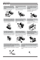
Safety Precautions n Operation Do not put a pet or house plant where it will be exposed to direct air flow. • It is not good to sit in the draft. Do not step on the indoor/outdoor unit and do not put anything on it. • It may cause an injury through dropping of the unit or falling down. Be cautious not to touch the sharp edges when installing. • A severe cut or other injury could result. Do not block the inlet or outlet of air flow. • It may cause product failure. Always insert the filter securely.
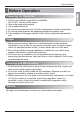
Before Operation Before Operation 1. Contact an installation specialist for installation. This is NOT a do-it-yourself project. 2. Plug in the power plug properly. 3. Use a dedicated circuit. 4. Do not use an extension cord. Consult a professional installer or electrician. 5. Do not start/stop operation by plugging/unplugging the power cord. 6. If the cord/plug is damaged, replace it with only an authorized replacement part. Usage 1.
Introduction Introduction Symbols Used in this Manual This symbol alerts you to the risk of electric shock. This symbol alerts you to hazards that could cause harm to the air conditioner. NOTICE This symbol indicates special notes. Features This appliance should be installed in accordance with the National Electric Code. Expanded Metal Grille Should be applied for better performance in PTAC and PTHP Units.
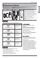
Electrical Safety Electrical Safety 115V~ 230V~ 265V~ Power cord may include a current interrupter device. A test and reset button is provided on the plug case. The device should be tested on a periodic basis by first pressing the TEST button and then the RESET button. If the TEST button does not trip or if the RESET button will not stay engaged, discontinue use of the air conditioner and contact a qualified service technician. NOTICE The shape may be different according to its model.
Electrical Safety Electrical Safety IMPORTANT (PLEASE READ CAREFULLY) FOR THE USER'S PERSONAL SAFETY, THIS APPLIANCE MUST BE PROPERLY GROUNDED The power cord of this appliance is equipped with a three-prong (grounding) plug. Use this with a standard three-slot (grounding) wall power outlet to minimize the hazard of electric shock. The customer should have the wall receptacle and circuit checked by a qualified electrician to make sure the receptacle is properly grounded.
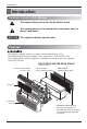
Installation Installation Dimension of air conditioner • There are sharp edges that can cause serious cuts. • If the unit is to be installed close to the seaside, it needs additional treatment on the heat exchanger. • When lifting the air conditioner, it is HEAVY. Use 2 people to lift. For existing sleeve, you should measure the wall sleeve dimensions. You can install the new air conditioner according to these installation instructions to achieve the best performence.
Installation • UNIT INSTALLATION 1. Remove the shipping screw from the ventilation door. 2. Remove the front gille by pulling it out at the bottom to release it, then lift it up along the unit top front. 3. Slide the unit into the wall sleeve and secure with 6 screws through the unit flange holes. 4. Reinstall the front grille by hooking the top over the unit top, then pushing it in at the bottom. • Failure to follow this caution may result in equipment damage or improper operation.
Control Locations Control Locations ENGLISH Manual Controls TEMPERATURE CONTROL Set the Thermostat control to the desired temperature mark 5 (the mid-point is a good starting position). If the room temperature is not satisfactory after a reasonable time, adjust the control to a cooler or warmer setting, as appropriate. OPERATION MODE SELECTOR OFF Turns air conditioner off. LOW FAN Low speed fan operation without cooling. HIGH FAN High speed fan operation without cooling.
Control Locations Electronic Controls The controls will look like one of the following. FAN SPEED • Every time you push this button, it cycles through the settings as follows: {High(F2) ’ Low(F1) ’ High(F2) ’ Low(F1)} E/SAVE 'F HEAT FAN HIGH COOL LOW TIMER MODE FAN TIMER POWER TEMP ON OFF • To turn the air conditioner ON, push this button. To turn the air conditioner OFF, push the button again. • This button takes priority over any other button.
Control Locations Self-Diagnosis USE: If the customer has to register a complaint to the service center, he can be very clear about registering the complaint that what is happening & by referring the user's manual the customer can clearly define the problem. So that the engineer should go fully prepared with the prescribed tools to be used regarding that problem. It also keeps the customer aware about the unit.
Control Locations Additional Controls • REMOVING THE FRONT GRILLE Additional controls are available after removing the front grille and option cover of control box. To remove the front grille, pull out the bottom of front grille and then lift up. To replace the front grille, place the tabs over the top of the unit and push the bottom of front grille until the clips snap into place. • ADDITIONAL CONTROLS The additional controls are located behind the option cover of control box.
Control Locations • REMOVING THE FRONT GRILLE ENGLISH Additional controls are available after removing the front grille and option cover of control box. To remove the front grille, pull out the bottom of front grille and then lift up. To replace the front grille, place the tabs over the top of the unit and push the bottom of front grille until the clips snap into place. • ADDITIONAL CONTROLS The additional controls are located behind the option cover of control box.
Control Locations • REMOTE/LOCAL CONTROL When remote/local switch #1 is on, it allow the unit to operate by the Remote Wall Thermostat. The unit control by knobs are not available. • ENERGY SAVER The energy saver switch #2 is on. This switch is set at cycle fan to provide continuous fan operation in cool or heat modes. When the switch is off the continuous fan allows continuous circulation of room air and make the more balanced temperature of the room.
Control Locations • REMOTE/LOCAL CONTROL • ENERGY SAVER The energy saver switch #2 is on. This switch is set at continuous fan to provide continuous fan operation in cool or heat modes. When the switch is off the continuous fan allows continuous circulation of room air and make the more balanced temperature of the room. When the switch is on the fan is on or off with the compressor or with the heater.
Control Locations Disassembly Instructions - Before the following disassembly, POWER SWITCH is set to OFF and disconnected the power cord. 1. Remove the front grille. 2. To remove the front grille, pull out the bottom of the front grille and then lift up. Re-install the component by referring to the removal procedure. 3. To replace the front grille, place the tabs over the top of the unit and push the bottom of front grille until the clips snap into place.
Maintenance and Service Maintenance and Service Air Filter Cleaning The air filter should be checked at least twice a month to see if cleaning is necessary. Trapped particles in the filter will build up and block the airflow. This reduces the cooling capacity and also causes an accumulation of frost on the cooling coils. If the filter becomes turn or damaged you should replace immediately. Replacement filters are available from your salesperson, dealer, and the authorized customer service centers. 1.
Maintenance and Service Drainage The base pan may overflow due to high humidity. To drain the excess water, remove the drain cap from the back of the unit. Drain Cap Chassis The chassis must be cleaned every four months or more often as the atmospheric conditions require. Use water and detergent to clean the basepan, center partition and coils. The use of harsh cleaning materials may cause a deterioration of the coil fins or endplates.
Maintenance and Service Common Problems and Solutions Normal Operation • You may hear a pinging noise caused by water being picked up and thrown by the slinger fan against the condenser on rainy days or when the humidity is high. This design feature helps remove moisture and improve efficiency. • You may hear the thermostat click when the compressor cycles on and off. • Water will collect in the base pan during high humidity or on rainy days.
Maintenance and Service COMPLAINT Fan motor noise. CAUSE REMEDY n Grommets • Check grommets; if worn or missing, replace them. n Fan • If cracked, out of balance, or partially missing, replace it. n Loose set screw • Tighten it. n Worn bearings • If knocking sounds continue when running or loose, replace the motor. If the motor hums or noise appears to be internal while running, replace motor. n Voltage • Check voltage. See the voltage limits. If not within limits, call an electrician.
Maintenance and Service COMPLAINT REMEDY n Voltage • Check the voltage. See the limits on the preceding page. If not within limits, call an electrician. n Overload • Check overload, if externally mounted. Replace if open. (If the compressor temperature is high, remove the overload, cool, and retest.) n Fan motor • If not running, determine the cause. Replace if required. n Condenser air flow restriction • Remove the cabinet.