
Engineering Data Guide
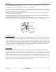
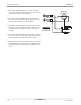


4) Remove both the power cord leads – one from the capacitor and
the other from the electronic board. And then install one power
cord lead to the center terminal of one fuse holder and the other
power cord lead onto the center terminal of the second fuse
holder as shown in the figure on the right.
5) Connect the BK-10 wire from the side terminal of one fuse hold-
er to the Line terminal on the electronic board.
6) Connect the RD-10 wire from the side terminal of the other fuse
holder to the Common (C) terminal on the capacitor.
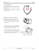
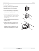
7) Place the control panel back to itʼs original position, taking care
not to pinch any wires. Align the panel and screw it firmly to
position with the original screws. Place the escutcheon and slide
the control knobs back to itʼs earlier position.
Installation Procedure(using a subbase):
The Installation and servicing of the equipment should be per-
formed by qualified and experienced personnel only.
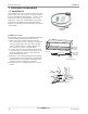
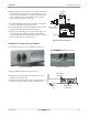
1) Remove both knockouts from the fuse holder location on the
subbase as shown on the right.
2) Install the fuse holders using the screws provided. The side con-
nector tab on the fuse holders should be towards the left.
Accessories 75
Controller accessories6RWU0-02A
PTAC
FUSEHOLDERS
Terminal Blocks Behind
the Control Panel
Status Light
Control Board
WH
GN
BK
Transformer
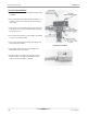
Fuse Holder
Knockouts
Leveling
Leg
Power Switch
Knockouts
Fig: Fuse Holder connections.
Fig: Front of subbase. Fig: Back of subbase.