
Engineering Data Guide


Accessories 79
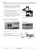
Controller accessories6RWU0-02A
PTAC
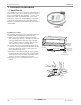
1.4 Power Switch
For both 208/230 and 265Volt power Switch
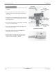
Assemblies
This optional kit can be installed in a full length subbase or
in the junction box of the Hard Wire Junction Box kit. This
switch has the Power On/Off function.
With each switch, a replacement junction box cover plate
has also been provided.
Note:
Unit terminals are not designed to accept conductors other
than copper. Use of other conductors may result in damage
of equipment.
All wiring must comply with applicable local and national
codes.
Installation Procedure:
The Installation and servicing of the equipment should be
performed by qualified and experienced personnel only.
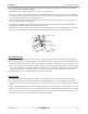
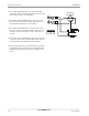
For 208/230 Volt Installation
1) At First, remove and discard the white lead of the Hard
wire assembly.
2) Connect the Black lead of the Hard wire assembly to one
terminal of the disconnect switch as shown in the figure
on the right.
3) Connect the red lead of the Hard wire assembly to the
terminal just opposite to the one, to which the black lead
has been connected.
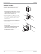
4) Remove the knockout from the desired power entry point
of the junction box and route the field supply power wires
into the junction box.
5) Connect the red and black leads of the field power supply
to the two unused terminals on the power switch.
6) Connect the ground wire of the field power supply to the
bare ground wire assembly.
7) Mount the switch on the tabs in the junction box and
install the switch cover plate provided with the power
switch.
Fig: Power Switch
Fig: 208/230V Power Switch