
Engineering Data Guide

Accessories 81
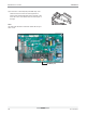
Controller accessories6RWU0-02A
PTAC
Power Switch installation for subbase
For 208/230 Volt
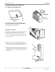
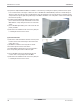
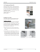
1) Remove the left and the right subbase cover panels by
removing the screws. Please retain the screws.
2) Remove the rectangular knockout located near the center
of the recessed area on the left cover panel.
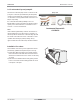
3) Install the switch using the two bolts and the two nuts pro-
vided so that the "On" position of the switch is on the
right. Install the ground lead between the switch mounting
tab and the mounting plate.
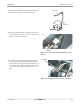
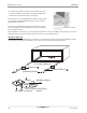
4) Route the RED wire, from the receptacle, through the bar-
rier in the subbase using the hole provided. (refer to figure
on the right)
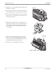
5) Insert the RED wire from the receptacle into the upper
right hole in the rear of the switch and tighten the screw.
Insert the RED power wire(field wiring) into the upper left
hole in the switch and tighten the screw.
6) Route the black wire, from the receptacle, through the
barrier in the subbase using the hole provided.
7) Insert the black wire, from the receptacle, into the lower
right hole in the rear of the switch and tighten the screw.
8) Attach the ground field wire by connecting the green wire
on the disconnect switch to the ground terminal on the
back wall of the subbase high voltage section.
9) And finally replace the cover panels (with the switch
installed) to the subbase using the screws removed in
step 1.
For 265 Volt
1) Remove the left and the right subbase cover panels by
removing the screws. Please retain the screws.
2) Insert the black wire from the receptacle into the lower
right hole in the rear of the switch and tighten the screw.
Insert the Black power wire(field wiring) into the lower left
hole in the switch and tighten the screw.
3) Connect the white wire, from the receptacle, to the white
power wire(field wiring) by means of the wire nut
4) Attach the ground field wire by connecting the green wire
on the disconnect switch to the ground terminal screw on
the back wall of the subbase high voltage section.
5) And finally replace the cover panels (with the switch
installed) to the subbase using the screws removed in
step 1.