To contact LG Electronics, 24 hours a day, 7 days a week: 1-800-243-0000 (US) Or visit us on the Web at: us.lge.com PORTABLE AIR CONDITIONER Para comunicarse con LG Electronics, 24 horas al día, 7 días a la semana: 1-800-243-0000 O visítenos en la Web en: us.lge.com USER’ S GUIDE & INSTALLATION INSTRUCTIONS ACONDICIONADOR DE AIRE PORTÁTIL English Please retain this ownerʼs manual for future reference. Read and follow all safety rules and instructions before using this product.
I N T RO D U C T I O N IMPORTANT SAFETY INSTRUCTIONS Basic Safety Precautions . . . . . . . . . . . . . . . . . . . 3, 4 Electrical Safety. . . . . . . . . . . . . . . . . . . . . . . . . . . 4, 5 PARTS AND FEATURES Key Parts and Components . . . . . . . . . . . . . . . . . . . 6 Control Panel and Remote . . . . . . . . . . . . . . . . . . . . 7 THANK YOU! Congratulations on your purchase and welcome to the LG family. HOW TO USE Before Using Your Air Conditioner . . . . . . . . . . . .
I M P O RTA N T S A F E T Y I N S T RU C T I O N S READ ALL INSTRUCTIONS BEFORE USE Your safety and the safety of others is very important. WARNING This symbol indicates the possibility of death or serious injury. CAUTION This symbol indicates the possibility of injury or damage to property. English We have provided many important safety messages in this manual and on your appliance. Always read and obey all safety messages. This is the safety alert symbol.
I M P O RTA N T S A F E T Y I N S T RU C T I O N S READ ALL INSTRUCTIONS BEFORE USE BASIC SAFETY PRECAUTIONS CAUTION To reduce the risk of fire, electric shock, or injury to persons when using this appliance, follow basic precautions, including the following: • To avoid possible cuts, avoid contacting the metal parts of the air conditioner when removing or reinstalling the filter. It can result in the risk of personal injury. • Do not block the air inlet or outlet of the air conditioner.
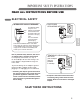
I M P O RTA N T S A F E T Y I N S T RU C T I O N S READ ALL INSTRUCTIONS BEFORE USE ELECTRICAL SAFETY For additional safety, the power cord features an integrated Reset circuit breaker. Test Test and reset buttons are provided on the plug case. The circuit breaker should be tested periodically by pressing the TEST button then the RESET button.
PA RT S A N D F E AT U R E S KEY PARTS AND COMPONENTS 1 CONTROL PANEL AND DISPLAY 1 Easy-to-read white LCD display shows the operatin state. Digital touch buttons make changing settings quick and easy. 2 2 MOTORIZED AIR DISCHARGE The adjustable louvered air discharge opens automatically when the air conditioner is turned on, and closes when it is turned off. It can also be set to oscillate to distribute air more evenly through the room.
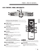
PART S AN D F EAT U R E S 5 A PART 7 1 6 4 3 English B PART Operation of functions is the same when using the remote or the control panel, unless otherwise stated. For detailed instructions on each function, see the follow ing pages 1 2 3 4 5 6 7 5 POWER ON/OFF Turns the air conditioner on and off. When turning on, a rising tone will sound to confirm. When turning off, a descending tone will sound.
H O W TO U S E BEFORE USING YOUR AIR CONDITIONER PREPARING FOR OPERATION UNPACKING THE AIR CONDITIONER Refer to the Installation Instructions included in this manual before using the air conditioner. Once the air conditioner has been properly assembled and installed: Remove and store packing materials for reuse. Remove any shipping tape before using the air conditioner. If the tape leaves behind any adhesive, rub a small amount of liquid dish soap onto it and wipe with a damp cloth.
H O W TO U S E BEFORE USING YOUR AIR CONDITIONER INSERTING BATTERIES IN THE REMOTE Before using your remote, install the provided AAA batteries: 1 Press and glide the battery cover on the back of the remote,then you can remove the cover. Be sure to note proper polarity! + 2 Insert two new alkaline AAA batteries into - the battery compartment, being sure to note the proper polarity. 3 Reattach the battery cover, making sure the 3 English locking tab clicks into place.
H O W TO U S E USING THE CONTROLS Control panel buttons shown. Operation using the remote control is the same, unless specifically noted.NOTE:The remote sensor is located under the air discharge and on the top of the front panel. POWER Press the POWER button to turn the air conditioner ON or OFF. When you turn the air conditioner on, an ascending tone will play and the LCD display will show the set temperature and any active mode.The air discharge on the top of the air conditioner wil automatically open.
H O W TO U S E FAN TIMER Pressing the FAN button cycles the circulation fan speed from low (F1) to medium (F2) to high (F3).The selected fan speed will be shown in the LCD display. The function can be used in either COOL or FAN modes. When changing fan speeds, there is a brief delay before the fan motor changes speed. When theTIMER function is selected, you can set the air conditioner to either automatically turn OFF or turn ON after a delay of up to 24 hours. The display will show 0.
HOW TO U SE USING THE CONTROLS AUTO CLEAN AUTO SWING • To turn the AUTO CLEAN function on, press the AUTO CLEAN button while the air conditioner is running in COOL,DRY or ENERGY SAVER mode. This function can only be selected from the remote;it is not available from the control panel.It must be set each time you wish to run the AUTO CLEAN function. AUTO CLEAN is used to remove moisture from the heat exchange coils. This helps prevent the formation of mildew and odors.
I N S TA L L AT I O N I N S T RU C T I O N S PREPARING FOR INSTALLATION WARNING The air conditioner is heavy! Use two or more people to lift and install the unit! Failure to do so could result in back injury or other injuries. EXHAUST COMPONENTS English The following c omponents are used for window venting. Not all compon ents are used for every installation.
I N S TA L L AT I O N I N S T RU C T I O N S WINDOW VENT PANEL AND EXTENSIONS The window installation kit allows you to install the air conditioner in most vertical-sliding windows 18" to 48" wide, or casement-style windows from 18" to 48" high. Small extension panel Vent Panel Vent Panel 18" 181⁄4" − 24" Vent Panel Small extension panel 181⁄4" − 24" For an 18" window opening, use the window vent panel by itself.
I N S TA L L AT I O N I N S T RU C T I O N S INSTALLATION IN VERTICAL SLIDING WINDOWS NOTE: The window installation kit can be used with vertical sliding windows between 18" and 48" wide. Foam seal C (Adhesive type-shorter) Extension panel (if required) Vent Panel 1 Cut the foam seal A(adhesive type) & C(adhesive type-shorter) to the proper length, and attach it to the window sash and frame. 2 Insert the vent panel assembly, including extension panels, if needed, into the window opening.
I N S TA L L AT I O N I N S T RU C T I O N S INSTALLATION IN VERTICAL SLIDING WINDOWS Type A screw 5 Install the security bracket with a type A screw, as shown. 6 Insert the oval end of the diffuser into the window installation kit until the locking tabs engage.
I N S TA L L AT I O N I N S T RU C T I O N S INSTALLATION IN CASEMENT STYLE WINDOWS NOTE: The window installation kit can be used with casement windows between 18″ and 48″ tall. Foam seal C (Adhesive type-shorter) Extension panel (if required) 1 Cut the foam seal A(adhesive type) & C(adhesive type-shorter) to the proper length, and attach it to the window sash and frame. 2 Insert the vent panel assembly, including extension panels, if needed, into the window opening.
I N S TA L L AT I O N I N S T RU C T I O N S INSTALLATION IN CASEMENT STYLE WINDOWS Type A screw 5 Install the window security bracket with a type A screw, as shown. 6 Insert the oval end of the diffuser into the window installation kit until the locking tabs engage.
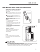
CARE AND CLEANING Your air conditioner is designed for year-round operation with only minimal cleaning and maintenance. For maximum efficiency, it is recommended that you have the cooling coils inspected and cleaned annually. Your local LG Authorized Service Center can provide this inspection and cleaning service for a nominal fee. WARNING • Unplug the air conditioner before cleaning or performing any maintenance or servicing.
CARE AND CLEARING EMPTYING THE WATER COLLECTION TANK Using the bottom drain port Drain Outlet Note: Drain Cap If the water full alarm is often on, there may be some malfunction about the unit. Contact the professional service for help. 5 6 7 8 drain location or outdoors. NOTICE end of the hose a suitable FL apperars in the display The water collection tank is full, drain the tank and reset your setting.
CARE AND CLEARING STORING THE AIR CONDITIONER If the air conditioner will not be used for an extended period of time: 1 Drain the water collection tank completely and leave the bottom drain cap and rubber plug long enough to allow any residual water to drain out. Once the tank is completely drained and no more water flows out, reinstall the rubber plug and cap. 2 Remove and clean the filter, allow it to dry completely, then reinstall it. 3 Remove the batteries from the remote.
T RO U B L E S H O OT I N G BEFORE CALLING FOR SERVICE Problem Possible Causes Solutions Air conditioner will not start • The air conditioner plug is not completely inserted in the electrical outlet. • Make sure electrical plug is plugged completely into a live, properly grounded outlet. • The house fuse is blown or the circuit breaker has tripped. • Replace the fuse or reset the circuit breaker. Make sure that there are no other appliances on the same circuit. • Power failure.
T RO U B L E S H O OT I N G BEFORE CALLING FOR SERVICE Problem Possible Causes Solutions F1, F2, or F3 • Air conditioner is in FAN mode and the number shown is the set fan speed. • This is normal. The air conditioner is working properly. FL • The water collection tank is ful l. • Empty the water collection tank. See the Care and Cleaning section. CH01 • Short or open circuit in the indoor air thermostat. • Unplug the air conditioner and contact your authorized LG service center.
LG ELECTRONICS, INC. PORTABLE AIR CONDITIONER LIMITED WARRANTY — USA Should your LG Portable Air Conditioner prove to be defective in material or workmanship under normal use during the warranty period listed below, effective from the date of original consumer purchase of the product, LG Electronics will replace the defective part(s). Replacement parts will meet intended fit and function of the original part. Replacement parts are warranted for the unexpired portion of the original warranty period.
I N T RO D U C C I Ó N INSTRUCCIONES DE SEGURIDAD IMPORTANTES Precauciones básicas de seguridad N. . . . . . . . 26, 27 Seguridad eléctrica . . . . . . . . . . . . . . . . . . . . . 27, 28 PIEZAS Y CARACTERÍSTICAS Piezas y componentes clave . . . . . . . . . . . . . . . . . 29 Panel de control y control remoto . . . . . . . . . . . . . 30 CÓMO UTILIZAR EL ARTEFACTO Antes de utilizar su acondicionador de aire . . . 31, 32 Cómo usar los controles . . . . . . . . . . . . . . . . .
I N S T RU C C I O N E S D E S E G U R I DA D I M P O RTA N T E S LEA TODAS LAS INSTRUCCIONES ANTES DE USAR Su seguridad y la seguridad de otros son muy importantes. Hemos incluido muchos mensajes de seguridad importantes en este manual y en su artefacto. Siempre lea y obedezca todos los mensajes de seguridad. Este es el símbolo de alerta de seguridad. Este símbolo lo alerta sobre peligros potenciales que pueden matarlo a lastimarlo a usted o a otros.
I N S T RU C C I O N E S D E S E G U R I DA D I M P O RTA N T E S LEA TODAS LAS INSTRUCCIONES ANTES DE USAR PRECAUCIONES BÁSICAS DE SEGURIDAD PRECAUCIÓN Para reducir el riesgo de incendio, descarga eléctrica o lesiones a personas cuando utilice este artefacto, deben seguirse precauciones básicas de seguridad, incluyendo las siguientes: • Para evitar posibles cortes, evite el contacto con las piezas metálicas del acondicionador de aire cuando quite o vuelva a instalar el filtro.
I N S T RU C C I O N E S D E S E G U R I DA D I M P O RTA N T E S LEA TODAS LAS INSTRUCCIONES ANTES DE USAR SEGURIDAD ELÉCTRICA DISYUNTOR INTEGRADO Para seguridad adicional, el cable de energía Reset cuenta con un disyuntor Test integrado. Los botones de prueba y de reconfiguración se encuentran en el enchufe. MÉTODO DE CONEXIÓN A TIERRA PREFERIDO Verifique que haya una conexión a tierra adecuada antes del uso.
P I E Z A S Y C A R AC T E R Í S T I C A S PIEZAS Y COMPONENTES CLAVE 1 1 PANEL DE CONTROL Y PANTALLA La pantalla digital de fácil lectura muestra la temperatura configurada y las luces indicadoras indican el modo de funcionamiento. Los simples botones de presión facilitan y aceleran los cambios de configuración. 2 2 SALIDA DE AIRE MOTORIZADA La salida de aire ajustable con rejillas se abre automáticamente cuando se enciende el acondicionador de aire, y se cierra cuando se lo apaga.
P I E Z A S Y C A R AC T E R Í S T I C A S PANEL DE CONTROL Y CONTROL REMOTO 5 A PARTE 7 1 6 4 3 B PARTE 1 2 POWER ON/ OFF(encendido/apagado) 5 Enciende y apaga el acondicionador de aire. Al encenderse, se oirá una señal sonora ascendente para confirmar. Al apagar, se oirá una señal sonora descendente. 6 AUTO CLEAN(autolimpieza) La función de AUTOLIMPIEZA sirve para eliminar la humedad del intercambiador de calor y ayudar a prevenir la formación de olor.
C Ó M O U T I L I Z A R E L A RT E FAC TO ANTES DE UTILIZAR EL ACONDICIONADOR DE AIRE PREPARACIÓN PARA LA OPERACIÓN Lea las Instrucciones de instalación incluidas en este manual antes de usar el acondicionador de aire. Una vez que el acondicionador de aire se ha montado e instalado correctamente: 1 Enchufe el cable de energía en un tomacorriente de uso exclusivo con adecuada conexión a tierra. Escuchará una señal sonora que confirma que el acondicionador está enchufado.
C Ó M O U T I L I Z A R E L A RT E FAC TO ANTES DE UTILIZAR EL ACONDICIONADOR DE AIRE CÓMO COLOCAR LAS BATERÍAS EN EL CONTROL REMOTO Antes de usar el control remoto, instale las baterías AAA provistas: 1 Presione la lengüeta de bloqueo de la tapa de las baterías en la parte trasera del control remoto y quite la tapa. + - 2 Introduzca dos baterías alcalinas nuevas AAA en el compartimento de las baterías, asegurando de utilizar la polaridad correcta.
C Ó M O U T I L I Z A R E L A RT E FAC TO CÓMO USAR LOS CONTROLES A continuació pueden verse los botones del panel de control. La operación con el control remoto es la misma, a menos que se especifique lo contrario. NOTA: El sensor remoto se encuentra debajo de la descarga de aire y de arriba del panel frontal. Siempre apunte el control remoto al sensor.
C Ó M O U T I L I Z A R E L A RT E FAC TO FAN SPEED (velocidad del ventilador) TIMER 1-24 Hr (temporizador 1-24 hs) Presionando el botón FAN SPEED la velocidad del ventilador de circulación pasa de baja (F1) a media (F2) a alta (F3). En la pantalla podrá verse la velocidad de ventilador seleccionada. La función puede utilizarse en los modos COOL (frío) o FAN (ventilador). Cuando se cambian las velocidades del ventilador, se produce una pequeña demora antes de que el motor las modifique.
C Ó M O U T I L I Z A R E L A RT E FAC TO CÓMO USAR LOS CONTROLES AUTO CLEAN(autolimpieza) AUTO SWING(balanceo automático) • Para encender la función de AUTO CLEAN, apriete el botón AUTO CLEAN, cuando el aire acondicionado está trabajando en modos de como FRESCO, SECO o AHORRO de ENERGÍA. Dicha función se selecciona sólo desde el panel. Se debe establecer nuevamente cada vez cuando quiere usted lanzar la función de AUTO CLEAN. La functión AUTO SWING solo puede activarse mediante el control remoto.
I N S T RU C C I O N E S D E I N S TA L AC I Ó N PREPARACIÓN PARA LA INSTALACIÓN ADVERTENCIA ¡El acondicionador de aire es pesado! ¡Utilice dos o más personas para levantar e instalar la unidad! No hacerlo puede provocar lesiones en la espalda u otras lesiones. COMPONENTES DE SALIDA Los siguientes componentes se usan para la ventilación de la ventana. No todos los componentes se utilizan en todas las instalaciones.
I N S T RU C C I O N E S D E I N S TA L AC I Ó N PANEL DE VENTILACIÓN Y EXTENSIONES DE LA VENTANA El equipo de instalación le permite instalar el acondicionador de aire en la mayoría de las ventanas de deslizamiento vertical de 18ʺ a 48ʺ de ancho, o ventanas deslizamiento horizontal de 18ʺ a 48ʺ de altura.
I N S T RU C C I O N E S D E I N S TA L AC I Ó N INSTALACIÓN EN VENTANAS DE DESLIZAMIENTO VERTICAL NOTA: El equipo de instalación en ventanas puede utilizarse con ventanas de deslizamiento vertical de un ancho de entre 18ʺ y 48ʺ. Tipo C de sellado con espuma (tipo adhesivo-más corto).
I N S T RU C C I O N E S D E I N S TA L AC I Ó N INSTALACIÓN EN VENTANAS DE DESLIZAMIENTO VERTICAL Soporte de seguridad Tornillos Tipo B tornillo tipo B, como puede verse. 6 Introduzca el extremo oval del difusor dentro del equipo de instalación en ventanas hasta que las lengüetas queden trabadas.
I N S T RU C C I O N E S D E I N S TA L AC I Ó N INSTALACIÓN EN VENTANAS DE DESLIZAMIENTO HORIZONTAL NOTA: El equipo de instalación de ventanas puede usarse con ventanas con bisagras con una altura de 18ʺ a 48ʺ. Sellado con espuma C (tipo adhesivom"s corto) Sellado con espuma A (tipo adhesivo) Panel de extensión (si fuera necesario) Panel de ventilación 1 Corte la espuma A (tipo adhesivo) y C (tipo adhesivo-más corto) según la longitud adecuada, y colóquelo en la hoja y el marco de la ventana.
I N S T RU C C I O N E S D E I N S TA L AC I Ó N INSTALACIÓN EN VENTANAS DE DESLIZAMIENTO HORIZONTAL Soporte de seguridad Tornillo Tipo B tornillo tipo B, como puede verse. 6 Introduzca el extremo oval del difusor dentro del equipo de instalación en ventanas hasta que las lengüetas queden trabadas.
C U I DA D O Y L I M P I E Z A Su acondicionador de aire está diseñado para funcionar durante todo el año con sólo una limpieza y mantenimiento mínimos. Para una eficiencia máxima, se recomienda que haga inspeccionar y limpiar las serpentinas de enfriamiento una vez por año. Su Centro de Servicio Autorizado LG local puede prestar este servicio de inspección y limpieza por una módica suma.
C U I DA D O Y L I M P I E Z A CÓMO VACIAR EL TANQUE DE RECOLECCIÓN DE AGUA Empleando el puerto inferior de drenaje Cuando el tanque interno de recolección de agua está lleno, aparecerá FL en la pantalla y el acondicionador de aire se apagará hasta que se vacíe el tanque. 1 Desenchufe el acondicionador de aire, desconecte la manguera de salida de la parte trasera, y traslade el acondicionador de aire a un lugar de drenaje adecuado o al exterior.
C U I DA D O Y L I M P I E Z A CÓMO GUARDAR EL ACONDICIONADOR DE AIRE Si no va a usar el acondicionador de aire durante un período prolongado: 1 Drene el tanque de recolección de agua completamente y deje el pico de drenaje destapado el tiempo suficiente para eliminar el agua residual. Una vez que el tanque se haya drenado por completo y no salga más agua, vuelva a colocar la tapa. 2 Quite y limpie el filtro, deje que se seque por completo y vuelva a instalarlo. 3 Quite las baterías del control remoto.
D E T E C C I Ó N D E P RO B L E M A S ANTES DE LLAMAR AL SERVICIO TÉCNICO Problema Causas posibles Soluciones El acondicionador de aire no se enciende • El enchufe del acondicionador de aire no está introducido del todo en el tomacorriente. • Verifique que el enchufe eléctrico esté conectado a un tomacorriente con tensión y adecuada conexión a tierra. • El fusible doméstico se ha quemado o el disyuntor ha saltado. • Cambie el fusible o vuelva a configurar el disyuntor.
D E T E C C I Ó N D E P RO B L E M A S ANTES DE LLAMAR AL SERVICIO TÉCNICO Problema Causas posibles Soluciones F1, F2, o F3 • El acondicionador de aire está en el modo FAN (ventilador) y el número en pantalla es la velocidad de ventilador configurada. • Esto es normal. El acondicionador de aire funciona correctamente. FL • El tanque de recolección de agua está lleno. • Vacíe el tanque de recolección de agua. Ver la sección Cuidado y limpieza.
LG ELECTRONICS, INC. ACONDICIONADOR DE AIRE PORTÁTIL –GARANTÍA LIMITADA – EE.UU. Si su acondicionador de aire portátil LG llegara a tener defectos en los materiales o en la mano de obra bajo un uso normal, durante el período de garantía establecido a continuación, vigente desde la fecha original de compra del producto, LG Electronics reemplazará las piezas defectuosas. Las piezas de reemplazo tendrán las mismas características y funciones de la pieza original.
MFL36812504_SP:Layout 1 P/No. MFl62172001 Printed in China 2007.12.