
Owner’s Manual
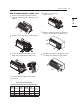
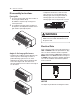


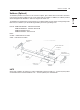
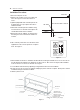
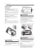
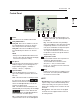

Table Of Contents

Attachment screw
subbase to side panel(2)
Attachment screw
subbase to Wall sleeve(2)
Adjustable Side
Extension Panel (2)
Wall Sleeve
Insulation
Electrical Subbase
Leveling Bolt
Access Cover
Leveling bolt
Installation Procedure:
1. Disconnect all power to unit.
2. Mark the hole location on sleeve then drill 1/8in
holes. See Figure 2 for hole dimensions on
sleeve.
3. (Optional) Adjustable side extension panels can
be attached to cover open space left between
subbase and wall.
4. Attach side extension panels to subbase using
one black screw on each side so that panel end
extends dimensions from the subbase.
5. Bring power into the subbase electrical junction
box using one of the knockouts for conduit con-
nections.
6. Take electrical junction box cover off and use field
supplied wire nuts to connect power to receptacle
wires. See Figure 3.
7. Attach subbase to wall sleeve. Subbase has side tabs for mounting the subbase to sleeve. Be sure hole on
the side tab is lined up with the pre drilled hole on side of sleeve. Once holes are aligned, attach subbase
to sleeve with one one screw on each side. See Figure 4.
8. Level subbase flush with floor by adjusting leveling bolts beneath each end of subbase.
9. Remove the access cover from the subbase and plug the power cord into receptacle. Route power cord out
of subbase through cord notch in subbase.
10. Restore power to unit.
SIDE VIEW OF WALL SLEEVE
1 3/16
”
1/2”
Inside Wall
1/8” Hole
Field Wiring
Line Voltage
NEMA 6-20R
Receptacle
230/208 VAC Field Schematic
NEMA 6-30R
Receptacle
16
INSTALLATION
Figure 2
Figure 3
Figure 4