
Engineering Data Guide

92 Accessories
Mechanical accessories 6RWU0-02A
PTAC
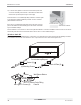
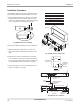
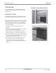
2.5 Leveling legs
Leveling legs are designed to provide extra front support
and leveling of the wall sleeve. Two leg assemblies are
needed by each unit and each leg assembly requires two
screws for attaching them to the wall .
These leveling legs must be installed before the installa-
tion of the chassis but after the wall sleeve is in position.
Holes must be drilled on each side of the wall sleeve
below the duct package holes, as shown on the figure on
the right, for attaching it to the wall sleeve.
Installation Procedure:
The Installation and servicing of the equipment should
be performed by qualified and experienced personnel
only.
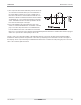
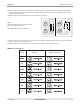
1) At first, drill two 1/8 – inch holes in each side of the
wall sleeve as shown in the figure on the right(using
the leveling leg assembly as a template). The holes
should be drilled near the front of the sleeve for the
leveling legs to provide better support to the wall
sleeve and the weight of the unit.
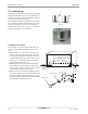
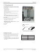
2) Adjust the leveling legs to the required height and
then install them on either side of the wall sleeve by
means of screws. Caulk or seal the screws to prevent
any water leaks from these screw points.
3) Adjust the level of the sleeve horizontally from side to
side. Provide a slight slope (one quarter bubble in the
sight glass) towards outside (other side of the room).
Check the level again after the unit has been installed
and adjust the legs further if necessary.
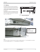
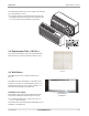
Leveling Legs
AYLL101
Adjuster Screw
Speed Grip Nut
Leveler Bracket
1/8" Diameter holes
(four required per unit field-drilled)
1"
1/4"
1/2"