
Engineering Data Guide


94 Accessories
Mechanical accessories 6RWU0-02A
PTAC
Installation Procedure:
The Installation and servicing of the equipment should be
performed by qualified and experienced personnel only.
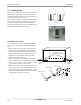
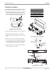
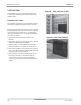
1) Remove parts B and C (refer to the figure on the right)
from the subbase and join together using two metal
screws. The resulting assembly now becomes the right
front cover (part F) as shown in the figure below.
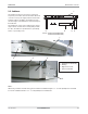
2) Position the subbase under the front of the wall sleeve.
3) Align the back edge of the flange on cover A to the
front of the wall sleeve flange(refer to the figure on the
right).
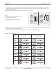
4) Drill four 1/8 inch holes in wall sleeve to line-up with
holes in subbase (location D) and then mount the sub-
base onto the wall sleeve with four sheet metal screws
provided with the kit (refer to the figure on top right).
5) Remove the left front cover from the subbase (refer to
part A on the figure on top right).
Part/Location Identification
A
B
C
D
E
F
Left Front Cover
Right Front Cover
Front Cord Panel
Wall Sleeve Hole Location
Skirting Hole Location
Right Cover Assembly
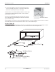
Wall Sleeve
Cover
Wiring
Access
Subbase
Box Assy
Low Voltage
Compartment
2-13/16"
(71 mm)
11-13/16"
(300 mm)
A
B
F
C
E
D
D
E
Wall Sleeve
(Outdoor Side)
Wall Sleeve
Inside Edge
Back of
Flange "A"
13 3/4"
2 3/4"
2 5/8"
13-7/8" (352 mm)
3-1/16"
(78 mm)
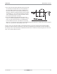
Left End View
Concentric
Knockouts In Bottom
Ground
Screw Location
Receptacle Provided
Inside subbase
Accessory
Top View
Concentric
Knockouts In Rear
Front View
20-5/16" (515.5 mm)
2" (50 mm) Max.
Adjustment
4" (101 mm)
2-5/8" (67 mm)
2" (50 mm)
2 3/4"
16"
16"
1-3/8" (35 mm)
Fig: Right Front Cover assembly
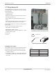
Fig: Subbase and itʼs components
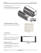
Fig: Dimensions of subbase