ENGLISH ESPAÑOL INSTALLATION MANUAL ELECTRIC RANGE Please read these instructions thoroughly before installing and operating the range. LRE3027ST LRE3025ST LRE3023ST LRE3023SB LRE3023SW LRE3021ST LRE3085ST LRE3083ST LRE3083SB LRE3083SW LDE3037ST LDE3037SB LDE3037SW LDE3035ST LDE3035SB LDE3035SW LDE3031ST LSE3092ST LSES302ST LRE6321ST LRE3083BD www.lg.com (REV.
TABLE OF CONTENTS TABLE OF CONTENTS 3 SAFETY 3 Before You Begin 3 Important Safety Instructions 5 Prepare to Install the Range 6 6 PREPARE TO INSTALL RANGE Installation Drawings 8 ELECTRICAL CONNECTIONS 8 Electrical Connection Requirements 8 Connect Range Cord 10 3-Wire Connection With a Power Supply Cord 11 4-Wire Connection With a Power Supply Cord 11 3-Wire Connection: Conduit 12 4-Wire Connection: Conduit 13 INSTALL THE RANGE 13 Anti-Tip Device Installation 13 Final Inst
SAFETY 3 Remove all tape and packing materials before using the range. Dispose of all plastic bags after unpacking the range. Never allow children to play with packing materials. You can download the installation and owner’s manual at: http://www.lg.com. IMPORTANT SAFETY INSTRUCTIONS Read and follow all instructions before using your oven to prevent the risk of fire, electric shock, personal injury, or damage when using the range. This guide does not cover all possible conditions that may occur.
SAFETY WARNING • P ower supply cord and plug should not be modified. If it will not fit the outlet, have a proper outlet Installed by a qualified electrician. • Using an extension cord to connect the power is prohibited. The way to connect the power cord and plug directly is strongly recommended. • Electrical ground is required on this appliance. • You should make sure that the power cord is not pinched by the range or heavy objects.
SAFETY 5 •T he information in this manual should be followed exactly. - A fire or electrical shock may result causing property damage, personal injury or death. WARNING Tip - Over Hazard A child or adult can tip the range and be killed. Verify the anti-tip bracket have been installed. Ensure the anti-tip bracket is enganged when the range is moved. Do not operate the range without the antitip bracket in place.
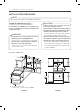
PREPARE TO INSTALL THE RANGE INSTALLATION DRAWINGS NOTE SAVE FOR THE USE OF THE LOCAL ELECTRICAL INSPECTOR CLEARANCES AND DIMENSIONS (Figure 1) To install range refer to the following Figure 1. For installation in CANADA, a Free-standing range is not to be installed closer than 15/32 (12mm) from any adjacent surface. WARNING •Y ou should use two or more people to move and install range. (Excessive Weight Hazard) - Failure to do so can result in back or other injury.
PREPARE TO INSTALL THE RANGE 7 ENGLISH For model : LSE Series 24” (60.9cm) A = 30”(76.2 cm) For U.S.A = 30”(76.2 cm) ~ 31”(78.7 cm) For CANADA FIGURE 1 Figure 2 For model : LDE Series Cabinet opening Wall Center 15”(38cm) 11”(28cm) Cabinet 4” (10cm) 6” (15.2cm) 9” (23cm) 2.5”(6.3cm) 4” (10cm) 5” (13cm) 6” (15.2cm) 9” (23cm) 2.5” (6.3cm) A = 30”(76.2 cm) For U.S.A = 30”(76.2 cm) ~ 31”(78.7 cm) For CANADA FIGURE 1 Figure 2 MINIMUM DIMENSIONS (Figure 2) * 30" (76.
ELECTRICAL CONNECTIONS ELECTRICAL CONNECTION REQUIREMENTS This appliance must be installed and grounded on a branch circuit by a qualified technician in accordance with the National Electrical code ANSI/NFPA NO. 70 latest edition. All wiring should conform to Local and NEC. This range requires a single-phase, 3 wire, A.C 120/208V or 120/240V 60Hz electrical system.
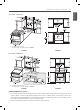
ELECTRICAL CONNECTIONS For model : LRE Series WARNING (LDE series only) •Y ou never remove the protec tion cover covering the rear of lower oven. - Failure to do so can result in serious damage to power cord. The damage causes serious burns and electric shock. For model : LSE Series 1 /8"(2.8cm) 11/8"(2.8cm) 13/8"(3.5cm) 11/8"(2.8cm) 13/8"(3.5cm) 13/8"(3.
ELECTRICAL CONNECTIONS 3-WIRE CONNECTION WITH A POWER SUPPLY CORD WARNING •T he middle (neutral or ground) wire, which is white, of a 3 wire power cord or a 3 wire conduit has to be connected to the middle post of the main terminal block. The remaining two wires of the power cord or conduit have to be connected to the outside posts of the main terminal connection block. - Failure to do so can result in electrical shock, severe personal injury or death.
ELECTRICAL CONNECTIONS WARNING • O nly a 4-conductor power-supply cord kit rated 120/240 volts, 50 amperes and marked for use with ranges with closed-loop connectors or openend spade lugs with upturned ends shall be used. The middle (neutral) wire, which is white, of the power cord or 4-wire conduit has to be connected to the middle post of the main terminal block. The other two wires of the power cord or conduit have to be connected to the outside posts of the main terminal connection block.
ELECTRICAL CONNECTIONS 4-WIRE CONNECTION: CONDUIT WARNING • T he middle (neutral) wire, which is white, of the power cord or 4-wire conduit has to be connected to the middle post of the main terminal block. The other two wires of the power cord or conduit have to be connected to the outside posts of the main terminal connection block. The 4th ground wire (green) must be connected to the frame of the range with the ground screw.
INSTALL THE RANGE WARNING Tip - Over Hazard A child or adult can tip the range and be killed. Verify the anti-tip bracket have been installed. Ensure the anti-tip bracket is enganged when the range is moved. Do not operate the range without the antitip bracket in place. Failure to follow these instructions can result in death or serious burns to children and adults. To check visually that leveling leg is inserted into bracket, grasp the top rear edge of the range and carefully attempt to tilt it forward.
MEMO
ESPAÑOL MANUAL DE INSTALACIÓN ESTUFA ELÉCTRICA Sírvase leer cuidadosamente estas instrucciones antes de instalar y poner a funcionar la estufa. LRE3027ST LRE3025ST LRE3023ST LRE3023SB LRE3023SW LRE3021ST LRE3085ST LRE3083ST LRE3083SB LRE3083SW P/No.: MFL57205804 LDE3037ST LDE3037SB LDE3037SW LDE3035ST LDE3035SB LDE3035SW LDE3031ST LSE3092ST LSES302ST LRE6321ST LRE3083BD www.lg.
2 ÍNDICE ÍNDICE 3 SEGURIDAD 3 Antes de Comenzar 3 Importantes Instrucciones de Seguridad 5 Preparativos Para Instalar la Estufa 6 6 PREPÁRESE PARA INSTALAR LA COCINA Esquemas de la Instalación 8 CONEXIONES ELÉCTRICAS 8 Requisitos para la Conexión Eléctrica 8 Conecte el Cable de la Cocina 10 Conexión de 3 Conductores con un Cable de Suministro Eléctrico 11 Conexión de 4 Conductores con un Cable de Suministro Eléctrico 11 Conexión de 3 Conductores: Tubo 12 Conexión de 4 Conductores: T
SEGURIDAD 3 ANTES DE COMENZAR Retire toda la cinta y los materiales de embalaje antes de utilizar la cocina. Puede descargar el manual de instalación en: http://www.lg.com. IMPORTANTES INSTRUCCIONES DE SEGURIDAD Lea y siga todas las instrucciones antes de usar su horno para evitar riesgos de incendios, descargas eléctricas, heridas a las personas o daños al utilizar la cocina. Esta guía no incluye todas las posibles situaciones que se podrían producir.
4 SEGURIDAD ADVERTENCIA • No se deben modificar el cable de alimentación ni el enchufe. Si el tomacorriente no coincide, asegúrese de que un electricista calificado instale un tomacorriente apropiado. • Se prohíbe utilizar un cable prolongador para conectar a la electricidad. Se recomienda enfáticamente que se conecten el cable de alimentación y el enchufe directamente al tomacorriente. • Este electrodoméstico requiere de conexión eléctrica a tierra.
SEGURIDAD PREPARATIVOS PARA INSTALAR LA ESTUFA ADVERTENCIA ADVERTENCIA RIESGO DE VOLCAR Un niño o un adulto pueden volcar el aparato y provocar su muerte. Verifique que los corchetes anti-vuelco han sido instalados. Asegurese que los corchetes anti-vuelcos estén ajustados cuando mueva el aparato. No haga funcionar el aparato sin que los corchetes anti-vuelco estén ajusados. No seguir estas instrucciones puede ser causa de muerte o graves quemaduras en niños o adultos.
6 PREPÁRESE PARA INSTALAR LA COCINA ESQUEMAS DE LA INSTALACIÓN NOTA RESERVADO PARA USO DEL INSPECTOR ELÉCTRICO LOCAL HOLGURAS Y DIMENSIONES (Figura 1) Consulte la figura 1 a continuación para la instalación de la estufa. No debe instalarse un cocina independiente a menos de 15/32 (12 mm) de cualquier superficie adyacente. ADVERTENCIA • P ara la instalación o para mover el horno, son necesarias dos personas.
PREPÁRESE PARA INSTALAR LA COCINA 7 Para el modelo : series LSE 24” (60.9cm) ESPAÑOL A = 30" (76,2 cm) para los EE.UU. = 30" (76,2 cm) ~ 31" (78,7 cm) para CANADÁ FIGURA 1 FIGURA 2 Para el modelo : series LDE Pared 15”(38cm) 11”(28cm) Gabinetes Cetro 6” (15.2cm) 4” (10cm) 9” (23cm) 2.5”(6.3cm) 4” (10cm) 5” (13cm) 6” (15.2cm) 9” (23cm) 2.5” (6.3cm) A = 30" (76,2 cm) para los EE.UU.
8 CONEXIONES ELÉCTRICAS REQUISITOS PARA LA CONEXIÓN ELÉCTRICA Un técnico calificado debe instalar y conectar a tierra este electrodoméstico en un circuito derivado de acuerdo con el código Eléctrico Nacional ANSI/NFPA Nº 70 - última edición. Todo el cableado debe adecuarse a los Códigos Eléctricos Nacionales y Locales. Esta cocina requiere de un sistema eléctrico monofásico de 3 conductores de corriente alterna de 120/208V o 120/240V 60Hz.
CONEXIONES ELÉCTRICAS La placa de conexiones se utiliza para la instalación del cable o tubo de alimentación. Para el cable de alimentación, instálelo con la placa de conexiones COMO ESTÁ INSTALADA. Para el tubo, extraiga la placa de conexiones y utilice el orificio para tubo (1 1/8”) en lugar del orificio para cable de alimentación (1 3/8” ). (Remítase a las Figuras 5 y 6). ADVERTENCIA (solo los series LDE) • N o retire nunca la cubierta de protección de la parte trasera inferior del horno.
10 CONEXIONES ELÉCTRICAS CONEXIÓN DE 3 CONDUCTORES CON UN CABLE DE SUMINISTRO ELÉCTRICO ADVERTENCIA • E l conductor central (neutro o tierra), de color blanco, de un cable de 3 conductores o un ducto para tres conductores debe conectarse en el polo central de la caja de terminales. Los dos conductores restantes del cable de alimentación o tubo deben conectarse a los bornes externos de la caja de conexión de terminales principal.
CONEXIONES ELÉCTRICAS CONEXIÓN DE 4 CONDUCTORES CON UN CABLE DE SUMINISTRO ELÉCTRICO ADVERTENCIA Instale el cable de alimentación de la siguiente manera: Para instalaciones con cable de alimentación, enlace el aliviador de tensión sobre el orificio para el cable de alimentación (13/8”) que se encuentra debajo de la parte trasera del horno. Inserte el cable de alimentación en el aliviador de tensión y ajústelo. (Remítase a la Figura 7.) NO instale el cable de alimentación sin un aliviador de tensión. 1.
12 CONEXIONES ELÉCTRICAS CONEXIÓN DE 4 CONDUCTORES: TUBO ADVERTENCIA • E l conductor central (neutro), de color blanco, de un cable de alimentación o un ducto para 4 conductores debe conectarse en el polo central de la caja de terminales. Los dos conductores restantes del cable de alimentación o tubo deben conectarse a los bornes externos de la caja de conexión de terminales principal. El cuarto conductor, para tierra (verde), se debe conectar al marco de la estufa con el tornillo de tierra.
INSTALE LA COCINA INSTALACIÓN DEL DISPOSITIVO ANTIVUELCO ADVERTENCIA A fin de examinar visualmente que el tubo nivelador posterior está introducido en el corchete, coja la esquina superior posterior del aparato e inclinela con cuidado hacia adelante. Soporte Antivuelco Tubo Ménsula Nivelador Anti-vuelco Pared Debe introducirse el tornillo en la madera o en el hormigón 1. Identifique el soporte con ayuda de la plantilla E l soporte antivuelco están embalados junto con la plantilla.
LG Customer Information Center 1-800-243-0000 USA, Consumer User 1-888-542-2623 CANADA 507-260-0000 PANAMA Register your product Online! www.lg.