OWNER’S MANUAL Hybrid Digital Video Recorder Please read this manual carefully before operating your set and retain it for future reference. MODELS LRH7160D Series LRH7080D Series *MFL67849056* 1512 (V8.
Safety Information 1 Safety Information 1 Safety Information This Class A digital apparatus complies with Canadian ICES-003. Cet appareil numérique de la classe A est conforme à la norme NMB-003 du Canada. CAUTION RISK OF ELECTRIC SHOCK DO NOT OPEN Warning: Do not install this equipment in a confined space such as a bookcase or similar unit. CAUTION: TO REDUCE THE RISK OF ELECTRIC SHOCK DO NOT REMOVE COVER (OR BACK) NO USER-SERVICEABLE PARTS INSIDE REFER SERVICING TO QUALIFIED SERVICE PERSONNEL.
Safety Information Disposal of your old appliance 2. Old electrical products can contain hazardous substances so correct disposal of your old appliance will help prevent potential negative consequences for the environment and human health. Your old appliance may contain reusable parts that could be used to repair other products, and other valuable materials that can be recycled to conserve limited resources. 3.
Safety Information Safety warnings and Cautions 1 Safety Information The following are warnings and cautions for the safety of the users and for the prevention of any property damage. Please read the following carefully. WARNING • Turn off the system before installation. Do not plug in several electric devices to the same outlet. -- • -• This may cause an explosion. If the system’s HDD exceeds its life span, you may not be able to recover any data stored inside the HDD.
Safety Information 5 CAUTION Please beware of the following precautions before installing the DVR. Avoid positioning the product in any place where the unit may come into contact with moisture, dust, or soot. • Avoid placing in direct sunlight or near heating appliances. • Keep the product away from electric sparks or magnetic substances. • Do not place any conductive material through the ventilation grills. • Keep the system turned off before installation.
Contents Contents 1 Safety Information 3 IMPORTANT SAFETY INSTRUCTIONS Screen on the Main Monitor 20 Main Monitor Screen 21 Moving the Channel's Position 21 Selecting the Main Monitor screen mode 22 Selecting the Spot Monitor screen mode 22 Grouping channel 22 PTZ Camera Control 24 Using the Digital Zoom function 24 Export the recorded data 25 Viewing the System Log List 26 Viewing System Information 26 Configuration menu 27 System settings 27 Properties Preparation 28 TCP
Contents 41 Event Popup 57 Supported PTZ Camera list 41 Notification 57 Supported IP Camera Audio/Video Codec 42 Mail 58 Time zones 42 Emergency 42 SNMP 59 Factory Default Configuration Settings 43 Output 66 Recording Time Table (250GB HDD) 43 Buzzer 69 IP Live/Playback Specifications 69 Specifications 44 User settings 44 Group Authority 44 User 45 Setup Wizard settings 45 Step 1 45 Step 2 46 Step 3 46 Step 4 46 Step 5 7 1 2 3 4 4 Operation 47 Instant Re
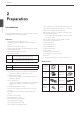
Preparation 2 Preparation 2 Preparation Introduction Model LRH7160D (16 Channel) is used for the description, operation and details provided in this operating guide. • Setup configuration export/import with USB memory stick. • Easy system S/W update with USB memory stick or network. • Clients S/W can manage max 300 DVR servers. • Max five clients can access one DVR server simultaneously. • Network bandwidth throttle.
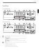
Preparation 9 Front Panel Front of the LRH7160D series NET a b c PTZ FOCUS+ d 1 2 3 4 INFO ALM.OFF FOCUS - IRIS - 5 6 ALARM LOG TEXT OFF 9 10/0 11 12 BACK UP NET COPY OSD MARK PTZ MOVE FOCUS+ TOUR IRIS+ HDD INFO ALM.
Preparation e Channel Buttons: You can input a number with channel buttons. You can also use the channel buttons for sub-function with SHIFT button (11 to 16 buttons of 8 channel DVR are used for sub-function without SHIFT button.). You should press the OK button after input the channel number when you select the applicable channel. • • 2 Preparation f The LED in the button indicates the status as follows: -- Off: The current status is for live mode. -- Red: Recording mode.
Preparation 11 Rear Panel Rear of the LRH7160D series a b c d 2 Preparation e f g hi j f k l m n o Rear of the LRH7080D series a e a f g b hi c j k l m n d o VIDEO INPUT: Connect the camera’s video output to these BNC connectors. b LOOP OUT: The signal from VIDEO INPUT connector is looped out to this connector. c RELAY-OUT Terminals: Output terminals for alarm (relay) signal. d Power Cord Inlet (AC IN): Connect the power plug.
Preparation Remote Control Button POWER (1) LOGIN Description Turns DVR on or off. Displays the User Log-In dialog box or logs out. 2 ID Preparation VIEW Displays the split mode menu for MAIN Monitor and SPOT Monitor. CAM Displays the Monitor menu to set the first camera channel. ALM.OFF OSD SETUP wsad OK COPY SEARCH MARK Cancels alarm activation and returns the system to the condition before the alarm was activated. Accesses or minimizes the system control bar. Displays the setup menu.
Installation 13 3 Installation Connections Precautions 3 Depending on the camera and other equipment there are various ways to connect the unit. Please refer to the camera manual or manuals for other devices as necessary for additional connection information. • Be sure to switch off the camera before installation and connection. Basic Connection Overview Connect the coaxial-type cameras Connect the Monitor, DVR, VCR, or others. Connect ATM/ POS unit. Connect the alarm (relay). Connect power cord.
Installation Connecting Camera Connecting Display device Connect the video output of your camera to the unit, using a standard 75 Ω video coaxial cable with BNC connector. LOOF OUT connector passes the video signal from VIDEO INPUT connector to connect to other device. This unit can be output simultaneously from the HDMI, VGA and SPOT OUT jack. The video signal connection between the DVR and the monitor.
Installation 15 HDMI Monitor connection Connect the unit to the HDMI monitor using a HDMI cable (Type A, High Speed HDMITM Cable). HDMI Monitor connection 3 SPOT USB Memory device Insert the memory device into the USB port. The system automatically recognizes the device. The system software can be easily upgraded using a USB memory device. Connecting Audio device Connect the AUDIO OUT jacks on the unit to the mono audio in jacks on your audio device.
Installation Connecting ATM/POS Connecting Network Connect the ATM/POS unit to the ATM/POS port. You can control and monitor the system via network. With the remote control (monitoring), you can change the system configuration or monitor the image via network. After the installation, check the network settings for the remote control and monitoring work.
Installation Connecting RS-485 device Connecting LKD1000 controller This DVR has two data terminals. Use this port to connect PTZ cameras, DVRs or keypads (optional). Connect the LKD1000 controller to control the DVR. (Refer to the manuals of the LKD1000 controller for more details.) The LKD1000 controller has to be connected to the 2 (DATA 2) port as shown illustration. If you connect the LKD1000 controller to the 1 (DATA 1) port, the LKD1000 controller will not be activated.
Installation Alarm Output Sensor input connection Connect the alarm device to the alarm output. Alarm signal outputs when an event occur. Alarm output connection 3 Installation Alarm device Alarm sensor Alarm sensor Terminal No.
Installation HDD INSTALLATION Note for Hard Disk Drive The internal hard disk drive (HDD) is a fragile piece of equipment. Please follow the guidelines below when using the DVR to protect against possible HDD failure. We recommend that you back up your important recordings onto an external backup device in order to prevent accidental loss. Make sure that the power is turned OFF when attaching or removing the HDD. Do not move the DVR while the power is on.
Installation System Operation 1. Turn on the unit. System booting will commence. The LG logo image will be displayed on the main monitor during the system booting. General Explanation of the Live Screen on the Main Monitor Main Monitor Screen 2. When the booting is completed the live window will be displayed. Click the icon on the system control bar or press a b cde f g h the LOGIN button on the remote control to display the log-in window. 3 Installation 3.
Installation You can control the PTZ Camera. (optional) You can use the video adjustment (Brightness, Contrast, Color) function. (Analog Channel Only) g Live Screen Displays the current surveillance live screen. h System Control Bar 21 Moving the Channel's Position You can change the camera channel's position in a split screen of the Main Monitor. 1. Select a desired channel by clicking the left button of the mouse. 2. Drag and drop it to a desired location and the channel's position will be changed.
Installation Selecting the Spot Monitor screen mode Grouping channel You can select the live screen mode to full, 4-split, 9-split, 16-split or 25-split screens on the spot monitor. You can group channels you want. 1. Press VIEW or click the icon in the system control bar. 2. Select [Spot Monitor]. 1. Press CAM or click the icon in the system control bar. 2. Select [Main Monitor] or [Spot Monitor] on the menu. 3. Select a camera number for including group. 3. Select a screen mode.
Installation You can adjust the focus of a camera manually. You can adjust the iris of a camera manually. Displays or disappear the preset control options in the virtual PTZ remote control 23 Preset Settings Preset position is the function to register camera monitoring positions (preset positions) associated with position numbers. By entering the position numbers, you can move cameras to the preset positions.
Installation Export the recorded data To Tour The Preset Positions You can tour all preset positions. 1. Press the TOUR button or Click the u icon. All registered preset positions in the camera will be selected and the camera position image will be switched on the active monitor. This unit can manually copy recorded images and audio from builtin HDD to the external recording devices. 1. Press COPY or click the icon in the system control bar. The [Video Export] menu appears. 2.
Installation NOTE • Check the export device before you proceed. • You can also use the COPY button on the front panel for export function. • You can export the recorded data only in the live mode. • If you use the external device, the external device has to be formatted on this unit. 25 Viewing the System Log List To view the system log list: 1. Press the LOG button or click the icon in the system control bar. The system log list window is displayed on the main monitor. 1.
Installation Viewing System Information To view system information: 1. Press the INFO button or click the icon in the system control bar. The system information window is displayed on the main monitor. Configuration menu The features and options of the DVR are configured through the menu. The operations of this unit can be set via a menu displayed on the main monitor.
Installation Setting the Menu Using the Front Panel Buttons or Remote Control Buttons Remote Control Front Panel Description 27 System settings Properties Use these buttons to select the menu options or adjust the options value. SEARCH VIEW SEARCH LOG-IN REC SETUP LOG-IN SEARCH BACK VIEW VIEW Select the option or confirm the setting. REC SETUP SETUP LOG-IN CAM CAM CAM REC BACK Return to the previous menu or level. BACK 3 Installation 1. Press SETUP to display the setup menu. 2.
Installation TCP/IP v4 Network • Interface: Select a LAN port you want to use (Ethernet 0 or Ethernet 1). • • DHCP: Select this option when a DHCP server is installed on the network to allow IP address assignment. With this setting, the IP address is assigned automatically. • IP Address: Enter the IP address. TCP/IP Port No.: Enter the TCP/IP Port number. You can watch the live surveillance image over the network with the PC Client program.
Installation please check network connection. When you want to change DDNS host name If you want to change the registered host name to new one, follow as shown below. 29 Date/Time 1. Enter a new host name in the [Host Name] option. 2. Press the [Update] button. The confirmation window will be displayed to change your host name. 3. Click the [OK] button. When host name is properly changed, the changed host name will be displayed in the [Registered Host] option.
Installation Controller 8. To confirm the latest version, click the [Check now for update] button to visit http://www.lgecommercial.com NOTE • Do not turn the power off during the update process to prevent the malfunction. • Do not remove the external device or CD/DVD disc for update while the update is in progress. It may cause a malfunction. Backup 3 Installation • IR Remote ID: Select the IR Remote ID for this unit. If you use multi systems set the IR Remote ID for each DVR unit.
Installation 8. Select the [Start Backup] icon and press OK to start backup. 9. Exit the setup menu. You can check the backup status on the system control bar in backup progress. Daily/Weekly backup NOTE • You cannot stop the backup when the backup is in progress. • The warning message will appear for the conditions listed below. 1. Connect the USB device for backup. You cannot use the CD or DVD writer for daily or weekly backup. 2. Select WEEKLY or DAILY on the schedule options. 3.
Installation Device settings PTZ Settings for the PTZ cameras connected via the data port of the RS-485 terminal. Camera 3 Installation • Ch: Displays the channel number. • Name : Set the channel name by using alphabetic letter, numeric digit and symbols up to 21 characters. • Channel: Selects the desired channel to set the connected PTZ camera. • Port: Selects the connected data port of the RS-485 terminal on the rear panel.
Installation IP Device Audio/Sensor setting You can configure this option when you select to [LGE] on the [Driver] option. Select [Audio/Sensor] tab of the [Setup] window. Audio In: Click the check box if you want to send the audio from the microphone input connector. -- Audio Type: Select the codec when you send the audio from the microphone input connector. -- Audio Out: Click the check box to output the audio from the speaker. -- Sensor: Select the sensor number on the drop-down list.
Installation -- • Compession (AXIS only): Enter the compression ratio of video. The lower value you set up, the higher definition picture you get. 6. Click the check box of confirmed cameras. Selected cameras are registered channel in order. 7. Click the [CLOSE] button to exit the window. Delete: Click the check box of the desired channel and then press the [Delete] button. Registered channel of IP Camera will be deleted. NOTE • The Supported IP camera specifications.
Installation • Parity: Select the desired parameter. The parity bit is added to the data, to perform parity check. Storage 35 Display settings OSD 3 Overwrite: Sets whether you use Overwrighting function. • Full Warning: When the HDD has overflowed a warning message is displayed. • Auto Delete: Sets the auto delete date. If you set the auto delete date, the recorded data will be deleted except the data within the selected date period of time.
Installation Video Adjustment Adjust the brightness, contrast and color settings of each camera channel. You can see the settings screen from the preview windows. Record settings Normal Schedule Recording A Normal schedule recoding can be activated at preset times, in a repeating pattern on selected weekdays. The DVR can record according to a schedule set by the user. It can also record manually regardless of date and time.
Installation 2. Select a recording mode. 37 NOTE In case you set the motion recording setting on the channel of IP camera, the recording starts when Video content analysis event as well as Motion event is occurred. 3. Drag and drop with left button of the mouse to set the channel and time you want to record. The color of the time block is changed depending on the selected mode. Gray (No recording): No schedule recording.
Installation Normal Settings concerning normal recording. 3 Installation 2. Enter the name of the special day. Use w/s/a/d to select the [Name] column and press OK. The virtual keyboard menu appears. 3. Use w/s/a/d to enter the necessary information for year, month and date. You can use the calendar icon to select the date. • CH: Displays the channel number. • Resolution: Selects the recording resolution. • Quality: Selects the recording picture quality. 4.
Installation Motion Instant/Panic Settings concerning motion recording. Settings concerning instant/panic recording. 39 3 CH: Displays the channel number. • CH: Displays the channel number. • Resolution: Selects the recording resolution. • Resolution: Selects the recording resolution. • Quality: Selects the recording picture quality. • Quality: Selects the recording picture quality • Frame Rate: Selects the frame rate. The frame rate is the number of recorded frames per second.
Installation Event settings Motion Sensor 3 Installation • Channel: Select the channel to set motion detection. • Sensitivity: Set the level of sensitivity for the created motion detection area. Sensitivity can be set from level 1 to 10 or OFF. • Relay Output: Select the number of the RELAY-OUT terminal for the output alarm (relay) signal when motion is detected. • Area: Select the desired motion detection area on the preview window screen.
Installation ATM/POS Data Format 41 Event Popup The DVR can be set to react to text input from devices such as ATMs (Automated Teller Machines) and POS (Point of Sale; i.e., cash registers). This screen allows you to configure the DVR for your input device. 3 • Input Channel: Select the mapping camera channel. • Transaction Start: Enter a Transaction Start string. Refer to the device manufacturer’s documentation for the text string that the device first sends when a transaction starts.
Installation Mail Emergency • Notification: Mark up to be notified the unit's operating information according to notification settings by e-mail. • • SMTP Server: Enter the SMTP Server address. If notification option is not mark up and the SMTP server option is empty, the SMTP Port, User Name, Password and TLS options cannot be set. Notification: Mark up to be notified the emergency agent about the unit's operating information according to your notification settings.
Installation • Trap Community String: Specifies the SNMP trap community in which you want to enable this system (e.g. lgecommunity or public). 43 Buzzer Marks up when you want to activate the selected option. Output 3 Relay Off -- ALARM ACKNOWLEDGE: Use the ALM.OFF button to stop alarm. -- POST-ALARM TIME: The alarm is stopped after post-alarm time. • System Alarm Out: Outputs the alarm (relay) signal via the selected alarm out terminal number when the system has some problem.
Installation User settings User You can set the user name for the selected User ID. Group Authority You can register a new user group with various access rights. 3 Installation 1. Select [User ID] from the drop-down list. 2. Enter the user name of the selected user ID. 3. Select the user group from the drop-down list. • Group ID: Select the group ID to assign authority. -- -- -- GUEST: The GUEST group has the limited authority of the system.
Installation Setup Wizard settings 45 Step 2 Set date and time. The Setup Wizard appears on the screen when you turn on the unit for the first time or select [Setup Wizard] on the Setup menu. You can set the System name, display language, date, time, network settings, recording schedule and recording mode on the initial setup wizard. NOTE If you run the Setup Wizard when DVR Setup has already been completed, the data previously configured could be deleted. 3 Set system name and display language.
Installation Step 3 Step 5 Set network address for LAN ports. Set recording mode for the Continuous and Event recording. • Interface: Select a LAN port you want to use (Ethernet 0 or Ethernet 1). • Resolution: Selects the recording resolution. • Quality: Selects the recording picture quality. • DHCP: Select this option when a DHCP server is installed on the network to allow IP address assignment. With this setting, the IP address is assigned automatically.
Operation 47 4 Operation Instant Recording NOTE Images from a camera will be recorded on the built-in hard disk. Ensure all the cameras are connected and that time and date have been set correctly. Before you start recording, first check the repeat recording settings in the recording menu of the system setup, and then make the recording settings. • External recording devices can be used as copy areas for images recorded on the hard disk.
Operation Instant Playback 7. Press ad (Play) button or click button to start playback. The picture(s) is (are) displayed on the main monitor. 8. Press STOP (Z) to stop playback and return to the search menu. It is possible to play a recorded image without stopping recording. 1. Select a channel you want to playback. 2. Press ad (Play) button to play a recorded image of the previous 1 or 2 minutes of recording. The playback image will be displayed on the full screen window. 3.
Operation • OK: Selects the column or confirms the setting. 5. Use w/s/a/d button to select the channel and press OK button to confirm the selection. If you want to select the all channels, marks up the [Select All] option. 49 ATM/POS Search Search the recorded text information by ATM/POS device. This function is available with backup data of the internal or external HDD only. 6. Select the [Event Type] from the drop-down list. 7. Select the [Search] button then press OK. The event list menu appears.
Operation Export Search Smart Search Searches an exported data in the external device or internal DVD-ROM device. If you want to use this function, you have to connect the external device or insert the CD/DVD disc with exported data otherwise the warning message will be displayed. Check the export device before you proceed. You can be searched the recorded data by specifying the motion detection conditions. 1. Press SEARCH or click [Search] menu appears. 4 Operation 1.
Operation Functions Available During Playback Button NET Playback Control Menu Remote Control PTZ Function FOCUS+ 2 3 4 INFO ALM.OFF FOCUS - IRIS - 5 6 LOG OSD Front panel 1 HDD Stops playback. ALARM BACK UP IRIS+ 7 8 TEXT OFF NET SET OSD CLEAR 1 9 10/0 11 COPY MARK HDD MOVE 12 INFO TOUR 5 13 14 15 16 Pauses playback. ALARMOSD NET 2 SHIFT ALM.OFF 6 LOG PTZ 9 1 BACK UP INFO HDD PTZ TEXT FOCUS+ OFF 10/0 3 2 COPY ALM.
Operation Using the playback control menu Using the Protect function You can use various playback function using playback control menu. This function allows you to protect the recorded data against being automatically overwritten. 1. Play a data recorded. Playback control menu appears at the bottom of the screen. How to select Protect section. 1. Click icon on the Playback control menu. The [Protect] menu appears. 2.
Troubleshooting 53 5 Troubleshooting Check the following guide for the possible cause of a problem before contacting service. Symptoms Cause & Solution Check the power cable is connected correctly. The system power does not turn on. Check the input voltage is correct. If the system power does not turn on even if the power cable is connected correctly, please contact the service center. Check the monitor power cable is connected properly. Make sure the monitor is turned on.
Troubleshooting Symptoms Cause & Solution Check the audio recording option is correctly set for the camera you wish to record audio. Audio data recorded with video data is not playing. Check the speaker and audio (line input) on the rear of system are connected correctly. Check the connected speaker is working properly. If the camera connected to the system has a problem, make sure whether the camera is damaged by trying to connect another camera to the video input jack.
Troubleshooting Symptoms 55 Cause & Solution E-mail reception failed without SMTP server setting. • Make sure the network is correctly set. • Make sure the mail address is input correctly. • Check the spam mail setting of the input mail address. (If you set the spam mail, some mails are deleted automatically or classified in the spam mail box) • Some of SMTP mail services do not support an E-mails from private SMTP servers. In this case use the public SMTP server.
Appendix 6 Appendix Recommended Devices Recommended USB Memory list No. Maker Model Name Capacity 1 LG Electronics XTICK SPIN 2G 2 LG Electronics XTICK UF1 32 G 3 Lexar Jump Drive 1G 4 Memorive SLC 2G 5 TRANSCEND JF 16 G 6 SKYDRV x2 2G 7 SANDISK Cruzer 16 G 8 Samsung Electronics SUM-LSB8 8G 9 Samsung Electronics SUM-PSB 32 G NOTE 6 Appendix • Some USB memory devices other than the ones on the above table may not work properly, even if this DVR reads them.
Appendix 57 Supported function list for device Device Instant backup Schedule backup Export Configuration Import/Export CD/DVD O X O X USB memory O O O O USB HDD O O O O E-SATA HDD O O O O NOTE If you use a USB memory stick or USB HDD for configuration import/export you must disconnect the other external USB devices.
Appendix Time zones Timezone Abbreviation Timezone Eniwetok, Kwajalein EK -12:00 Midway Island, Samoa MIS -11:00 Hawaii HAW -10:00 Alaska ALA -09:00 -08:00 Pacific Time (US and Canada); Tajuana PST -08:00 -07:00 Mountain Time (US and Canada), Chihuahua, La Paz, Mazatlan, Arizona MST -07:00 -06:00 Central Time (US and Canada), Saskatchewan, Guadalajara, Mexico City, Monterrey, Central America CST -06:00 -05:00 Eastern Time (US and Canada), Indiana (East), Bogota, Lima, Quito
Appendix 59 Factory Default Configuration Settings 1st level 2nd level Properties TCP/IP4 TCP/IP6 Network Default Value Factory Default setting System Name NULL YES Language The option depends on the model.
Appendix Network Streaming Date/Time NTP 6 Appendix System Controller Update Backup CH - - Resolution 352x240 (NTSC) / 352x288 (PAL) YES Quality STANDARD YES Frame Rate 7.5 (NTSC) / 6 (PAL) YES Profile Profile1 YES Date Current Date NO Time Current Time NO Date Format YYYY/MM/DD YES Time Format 12 HR YES Time Zone The option depends on the model.
Appendix Backup Camera PTZ Device IP Device ATM/POS Start Backup - - Erase Media - - Ch - Name CH 01 to CH 24 YES Audio 01 to 16, OFF YES IP Enable ON, OFF YES Channel CH 01 - Port NONE YES Control ID 0 YES Protocol LG_MULTIX YES Baud Rate 9600 YES PTZ Test - - CH 9 to 24 - Name CH 09 to CH 24 YES Model Name NULL YES MAC NULL YES IP NULL YES HTTP Port 80 YES 6 Driver LGE YES Profile 1 NULL YES Appendix System 61 Profile 2 NULL YES RTSP
Appendix Device Storage OSD Display Sequence 6 Appendix Video Adjustment Normal Schedule Record Special Schedule Normal Overwrite ON YES Full Warning OFF YES Auto Delete OFF YES Storage Saving OFF NO Format - - E-SATA - - Insert - - Eject - - Channel Name ON YES Channel Status ON YES Channel FPS ON YES Channel Name (Spot) ON YES Font Size 12 YES Position TOP YES Main Dwell Time 2 SEC YES Spot Dwell Time 2 SEC YES Channel CH 01 - Brightness
Appendix Motion Record Text Instant/Panic Sensor Event Motion CH - - Resolution 704x480 (NTSC) / 704x576 (PAL) YES Quality STANDARD YES Frame Rate 15 (NTSC) / 12.5 (PAL) YES Prealarm 10 SEC YES Postalarm 10 SEC YES CH - - Resolution 704x480 (NTSC) / 704x576 (PAL) YES Quality STANDARD YES Frame Rate 15 (NTSC) / 12.
Appendix Input Channel 01 - Transaction Start NULL YES Transaction End NULL YES Delimiter CARRIAGE RETURN YES Ignore String NULL YES Time Out 10 MIN YES Relay Output NONE YES Spot Channel OFF YES Sensor On OFF YES Motion Detection OFF YES Text In OFF YES Admin Password Changed OFF YES Video Loss OFF YES Power On/Off OFF YES Disk Full OFF YES Notification OFF YES SMTP Server NULL YES 6 SMTP Port 25 YES Appendix User Name NULL YES Password NULL
Appendix SNMP Event Output Buzzer User User NONE YES Port 161 YES Community String public YES User NULL YES Authentication NONE YES Password NULL YES Privacy NONE YES Password NULL YES Trap IP Address NULL YES Trap Community String NULL YES Relay Off ALARM ACKNOWLEDGE YES System Alarm Out NONE YES HDD Fail Alarm Out NONE YES Video Loss Alarm Out NONE YES Sensor OFF YES Motion OFF YES Text OFF YES System OFF YES Group ID GUEST YES Group Name GUE
Appendix Recording Time Table (250GB HDD) Recording Time (Hr) FPS Resolution (NTSC/PAL) Lowest Low 6 Appendix 352x240 /352x288 Video (NTSC/PAL) Quality Normal High Highest Video + Audio (NTSC/PAL) (8 CH, Video) (16 CH,Video) (8 CH, Video+Audio) (16 CH, Video+Audio) NTSC/PAL NTSC/PAL NTSC/PAL NTSC/PAL NTSC PAL 30.0 25.0 699.75 711.50 349.88 355.75 538.15 545.07 269.07 272.53 15.0 12.5 1119.60 1166.25 559.80 583.13 756.24 777.24 378.12 388.62 10.0 8.0 1393.
Appendix Resolution (NTSC/PAL) Video (NTSC/PAL) Quality Low Normal High Highest Video + Audio (NTSC/PAL) (8 CH, Video) (16 CH,Video) (8 CH, Video+Audio) (16 CH, Video+Audio) NTSC/PAL NTSC/PAL NTSC/PAL NTSC/PAL NTSC PAL 30.0 25.0 357.94 356.09 178.97 178.05 310.28 308.89 155.14 154.44 15.0 12.5 564.38 583.56 282.19 291.78 454.33 466.69 227.17 233.34 10.0 8.0 705.04 725.91 352.52 362.95 541.27 553.48 270.64 276.74 7.5 6.0 834.81 826.30 417.41 413.15 614.
Appendix Recording Time (Hr) FPS Resolution (NTSC/PAL) Lowest Low 6 Appendix 704x480 /704x576 Video (NTSC/PAL) Quality Normal High Highest Video + Audio (NTSC/PAL) (8 CH, Video) (16 CH,Video) (8 CH, Video+Audio) (16 CH, Video+Audio) NTSC/PAL NTSC/PAL NTSC/PAL NTSC/PAL NTSC PAL 30.0 25.0 240.47 237.62 120.24 118.81 217.98 215.63 108.99 107.82 15.0 12.5 379.82 388.56 189.91 194.28 326.58 333.02 163.29 166.51 10.0 8.0 474.58 483.24 237.29 241.62 394.28 400.
Appendix 69 IP Live/Playback Specifications Calculation formula: Total Available FPS for new resolution = (704 * 480) * (30 * IP Channels) / (Width * Height) IP Camera Live/Playback Display. (Codec: H.
Appendix Recording (Analog) Up to 480 IPS @ 352x240 Up to 480 IPS @ 704x240 Up to 480 IPS @ 704x480 Up to 240 IPS @ 352x240 Up to 240 IPS @ 704x240 Up to 240 IPS @ 704x480 PAL Up to 400 IPS @ 352x288 Up to 400 IPS @ 704x288 Up to 400 IPS @ 704x576 Up to 200 IPS @ 352x288 Up to 200 IPS @ 704x288 Up to 200 IPS @ 704x576 Frame Rate (/Second) Playback Speed Search NTSC FF/ Reverse 4 Steps (1x - 16x) Frame Advance Forward / Backward Screen Division Full, 4, 9, 16, 25 Search Mode 480 IPS (Rea