website http://www.lgservice.com MICROWAVE OVEN SERVICE MANUAL MODEL : LRMM1430SW LRMM1430SB CAUTION BEFORE SERVICING THE UNIT, READ THE SAFETY PRECAUTIONS IN THIS MANUAL.
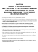
CAUTION WARNING TO SERVICE TECHNICIANS PRECAUTIONS TO BE OBSERVED BEFORE AND DURING SERVICING TO AVOID POSSIBLE EXPOSURE TO EXCESSIVE MICROWAVE ENERGY a. Do not operate or allow the oven to be operated with the door open. b.
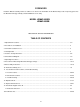
FOREWORD Read this Manual carefully. Failure to adhere to or observe the information in this Manual may result in exposing yourself to the Microwave Energy normally contained within the oven cavity. MODEL LRMM1430SW LRMM1430SB MECHANICAL SERVICE INFORMATION TABLE OF CONTENTS 1. Adjustment Procedures ....................................................................................................................................... 3-4 2. Precautions on Installation .....................................
ADJUST THE LATCH AND SWITCH CLOSINGS 1. ADJUSTMENT PROCEDURES To avoid possible exposure to microwave energy leakage, adjust the door latches and interlock switches, using the following procedure. (3) Loosen the screw holding the plastic latch board as shown. (4) With the oven door closed tightly, move the latch board upward toward the top of the oven and/or away from the door latch until the gaps are less than 1/64” (0.5 mm). ONLY AUTHORIZED SERVICE PERSONNEL SHOULD MAKE THIS ADJUSTMENT.
LATCH BOARD SECONDARY INTERLOCK SWITCH DOOR LATCH MONITOR INTERLOCK SWITCH PRIMARY INTERLOCK SWITCH Figure 1-a LATCH (B) 0-1/64" LATCH BOARD (A) 0-1/64" -4- Figure 1-b
2. PRECAUTIONS ON INSTALLATION 4. TRIAL OPERATION (Figure 2) A. Plug the power supply cord into a 120 V AC, 60 Hz, single-phase power source with a capacity of at least 20 amperes. B. Since the unit weights about 38 lbs., be sure to place it on a sturdy and flat surface. C. Avoid placing the unit in a location where there is direct heat or splashing water. D. Place the unit as far away as possible from TV, radio, etc. to prevent interference.
SPECIFICATIONS Rated Power Consumption Output Frequency Power Supply Rated Current Magnetron Cooling Microwave Stirring Rectification Door Sealing Safety Devices Magnetron Cavity Lamp Timer Tray Overall Dimensions Oven Cavity Size Effective Capacity of Oven Cavity Accessories 1250W maximum 1200W maximum (*IEC 60705 Rating standard) Adjustable 0W through 1200W, 10 steps 2,450 MHz 50 MHz 120V 12V AC, 60Hz 11 Amp.
6. OVERALL CIRCUIT DIAGRAM A.
B.
7. OPERATING PROCEDURES A. CONTROL PANEL 2 3 4 5 9 6 7 8 10 1 11 12 14 13 15 16 17 18 Figure 5. 1. Display. The Display includes a clock and indicators that tell you time of day, cooking time settings, and cooking functions selected. 2. Sensor Touch. This pad allows you to cook most of your favorite foods without having to select cooking times and power levels. 3. Homemade Bakery. Homemade bakery has 3 food categories of preset cooking time and power level. 4. Chicken Choices.
(9) STOP/CLEAR Key Used to stop the oven or clear all entries except CLOCK. B. PANEL INSTRUCTIONS (Figure 5) The entire operation is done by simple touch control pads. (1) Display Window Numbers and letters explained in Figure 5 are shown in the display window (Vacuum Fluorescent Tube). (a) The Time in four digits (12-hour indication): 00 Hour 00 Minute. (b) Cooking Time of Day in four digits 00 Minutes 00 Seconds.
C. EASY USE CHART (1) CLOCK 1. Touch STOP/CLEAR. 2. Touch CLOCK. 3. Touch numbers for correct time of day. 4. Touch CLOCK. (6) MELT 1. Touch STOP/CLEAR. 2. Touch MELT. Four different melt menus are provided. 3. Select Menu 1 to 4- See cooking guide. 4. Enter the amount of the Category. (2) “HI-POWER” COOKING 1. Touch STOP/CLEAR. 2. Touch COOK TIME. 3. Touch numbers for desired cooking time. 4. Touch START. (7) AUTO DEFROST 1. Touch STOP/CLEAR. 2. Touch AUTO DEFROST.
8. PROCEDURE FOR MEASURING MICROWAVE ENERGY LEAKAGE A. CAUTIONS (1) Be sure to check a microwave emission prior to servicing the oven if the oven is operative prior to servicing. (2) The service personnel should inform the manufacturer, importer, or assembler of any certified oven unit found to have a microwave emission level in excess of 5mW/cm.sq. and should repair any unit found to have excessive emission levels at no cost to the owner and should ascertain the cause of the excessive leakage.
G. POWER OUTPUT MEASUREMENT Be sure oven cavity is clean and cool . (not used recently) D. MEASUREMENT WITH A FULLY ASSEMBLED OVEN (1) After all components, including the outer panels, are fully assembled, measure for microwave energy leakage around the door viewing window, the exhaust opening and air inlet openings. (2) Microwave energy leakage must not exceed the values prescribed below. NOTES: Leakage with the outer panels removed - less than 5mW/cm.sq.
9. DISASSEMBLY INSTRUCTIONS Remove deco front IMPORTANT NOTES: UNIT MUST BE DISCONNECTED FROM ELECTRICAL OUTLET WHEN MAKING REPAIRS, RE-PLACEMENTS, ADJUSTMENTS AND CONTINUITY CHECKS. WAIT AT LEAST ONE MINUTE, UNTIL THE HIGH VOLTAGE CAPACITOR IN THE HIGH VOLTAGE POWER SUPPLY HAS FULLY DISCHARGED. THE CAPACITOR SHOULD BE DISCHARGED BY USING INSULATED WIRE - I.E. TEST PROBE CONNECTED TO 10K-OHM RESISTOR IN SERIES TO GROUND.
C. (1) (2) (3) (4) REMOVING CONTROL CIRCUIT BOARD (Figure 10) Remove out case. Remove door assembly. Unfasten two screws. Lift up and pull out control panel assembly carefully from the cavity. (5) Remove door frame. (6) Remove the F.P.C connector from the terminal socket. (7) Unfasten two screws which tighen the circuit board. (8) Remove control circuit board from the door panel assembly. D. (1) (2) (3) (4) (5) (6) (7) SEPARATE CAVITY AND BASE PLATE (Figure 11) Remove out case. Remove Door Assembly.
E. AIR GUIDE REMOVAL (Figure 12) (1) Separate cavity and base plate. (2) Unfasten the screws which hold the air guide in the base plate. (3) Unfasten the air guide from hook. G. (1) (2) (3) (4) F. POWER BOARD AND INVERTER MODULE AND SUCTION GUIDE (Figure 12) (1) Separate cavity and base plate. (2) Remove air guide. (3) Unfasten the screws. (4) Lift up the power board, inverter module and suction guide. SENSOR DUCT REMOVAL (Figure 13) Remove out case. Unfasten the sensor duct screw.
H. MAGNETRON REMOVAL I. REMOVING THE TURNTABLE MOTOR (1) Disconnect the leadwire from the magnetron. (2) Carefully remove the mounting screws holding the magnetron at the waveguide. (3) Remove the magnetron from the waveguide. (1) Remove the turntable and turntable roller rest. (2) Lay the unit down on its back. (3) Remove the turntable motor cover. The turntable base cover is easily removed by pinching the four parts with a wire cutting. (4) Disconnect the leadwire from the turntable motor terminals.
J. FAN MOTOR ASSEMBLY REMOVAL K. INTERLOCK SYSTEM (1) Separate cavity and base plate. (2) Remove air and suction guide.. (3) Remove the two screws holding the fan motor ASSEMBLY to the suction guide ASSEMBLY. (4) Disconnect the wires and unfasten the screws. (5) Pull out the Fan motor from the suction guide.
10. INTERLOCK CONTINUITY TEST WARNING : FOR CONTINUED PROTECTION AGAINST EXCESSIVE RADIATION EMISSION, REPLACE ONLY WITH IDENTICAL REPLACEMENT PARTS. TYPE NO. SZM-V 16-FA-63 OR VP-533A-OF OR V-5230Q FOR PRIMARY SWITCH TYPE NO. SZM-V 16-FA-62 OR VP-532A-OF OR V-5220Q FOR MONITOR SWITCH TYPE NO. SZM-V 16-FA-63 OR VP-533A-OF OR V-5230Q FOR SECONDARY SWITCH A. PRIMARY INTERLOCK SWITCH TEST B.
11. TEST AND CHECKOUT PROCEDURES, AND TROUBLESHOOTING CAUTIONS 1. DISCONNECT THE POWER SUPPLY CORD FROM THE OUTLET WHENEVER REMOVING THE OUTER CASE FROM THE UNIT. PROCEED WITH THE TEST ONLY AFTER DISCHARGING THE HIGH VOLTAGE CAPACITOR AND REMOVING THE LEAD WIRES FROM THE INVERTER MODULE. 2. ALL OPERATIONAL CHECKS WITH MICROWAVE ENERGY MUST BE DONE WITH A LOAD (1 LITER OF WATER IN CONTAINER) IN THE OVEN. A.
COMPONENTS TEST PROCEDURE RESULTS Antenna Gasket Chassis Filament NOTE: When testing the magnetron, be sure to install the magnetron gasket in the correct position and be sure that the gasket is in good condition. SENSOR 1. Disconnect sensor connector from micom computer board. 2. Measure resistance terminal to terminal (Select the ohm scale on the meter) Normal: Approximately BK-RD: 5.2 Kohms RD-WH: 2.1 Kohms BK-WH: 2.
COMPONENTS RELAY TEST PROCEDURE Check for continuity of relay with an ohm-meter. (Remove lead wires from relay and operate the unit.) RESULTS Normal: Approx. ON: 0 ohm OFF: ∞ ohms Abnormal: Infinite or several ohms. Relay 2 FAN MOTOR (Wire leads removed) Measure the resistance. (Ohm-meter scale: R x 100) A(RD) B(BK) Normal: Approx. 50 ~ 150 ohms Abnormal: Infinite or several ohms. C(WH) TURNTABLE MOTOR (Wire leads removed) Measure the resistance. (Ohm-meter scale: R x 1000) Normal: Approx.
B. CHECKOUT PROCEDURES (1) CHECKOUT PROCEDURES FOR FUSE BLOWING CAUTION: REPLACE BLOWN FUSE WITH 20 AMPERE FUSE. PROBLEMS Fuse blows immediately after the door is closed. Fuse blows immediately after the door is opened. Fuse blows when the door is closed and START key is touched. CAUSES Improper operation of the primary interlock, secondary interlock switches and/or the interlock monitor switch. Malfunction of the Inverter, the magnetron, the fan motor or the circuit board.
(2) CHECKOUT PROCEDURES FOR RELAY - PROBLEM (A) FAN motor and oven lamp turn on without touching START key when the door is closed. NO GOOD YES Remove the mate connector of I/O CON from the circuit board does the unit still operate? NO Replace the circuit board - PROBLEM (B) FAN motor and oven lamp turn on When the door is closed and START key is touched. NO YES Check the interlock switches GOOD NO Replace the micro switches.
(3) CHECKOUT PROCEDURES FOR CIRCUIT BOARD The following symptoms indicate a defective circuit board. (1) Check the input current. If the input current is more than 20A, check the magnetron and wiring. If the input current is less than 0.5 A, there is no input to the inverter. (2) The start function fails to operate but the interlock switches, the door sensing and the relay check good. (3) The unit with a normal relay continuously operates. (4) The buzzer does not sound or continues to sound.
C. TROUBLE SHOOTING WHEN YOU GET A COMPLAINT FROM YOUR CUSTOMER, EVALUATE THE COMPLAINT CAREFULLY. IF THE FOLLOWING SYMPTOMS APPLY, PLEASE INSTRUCT THE CUSTOMER IN THE PROPER USE OF THE MICROWAVE OVEN. THIS CAN ELIMINATE AN UNNECESSARY SERVICE CALL. CAUTIONS 1. Check grounding before checking for trouble. 2. Be careful of the Inverter. 3. When checking the continuity of the switches or of the inverter, disconnect one lead wire from these parts and then check continuity with the AC plug removed.
(TROUBLE 1) The following visual conditions indicate a probable defective control circuit. 1. Incomplete segments. • Segment missing. • Partial segment missing. • Digit flickering (NOTE: Slight flickering is normal.) 2. Colon does not turn on or blink. 3. A distinct change in the brightness of one or more numbers in display. 4. One or more digits in the display are not lighting. 5. Display indicates a number different from one touched, for example, key in 5 and 3 appears in the display. 6.
(TROUBLE 2) Oven does not operate at all, Display window does not display any figures, and no input is accepted. CONDITION 1. Fuse blows. CHECK Check continuity of monitor switch (with door closed). RESULT Continuity. CAUSE REMEDY Malfunction of the monitor switch. Replace fuse, primary, monitor switches, and RELAY of P.C.B Assembly. Shorted contact at the primary switch. Replace fuse, primary, monitor switches, and RELAY of P.C.B Assembly. No continuity.
(TROUBLE 3) Display shows all figures set, but oven does not start cooking while desired program times are set and START pad is touched. CONDITION CHECK 1. Setting time does not count down when touching START pad. Check continuity of secondary switch (with door closed). 2. Fan motor or oven lamp do not turn on. RESULT No continuity. CAUSE REMEDY Defective secondary switch. Replace secondary switch. Continuity. Check the connection between CN1 connector and PCB assembly.
(TROUBLE 5) No microwave oscillation even though oven lamp and fan motor run. (Display operates properly) CONDITION No microwave oscillation. CHECK Disconnect the wire leads from relay and check continuity of relay. (Operate the unit) RESULT CAUSE No continuity. Defective PCB assembly. Continuity. Replace Inverter and Magnetron. REMEDY Replace PCB assembly. NOTE : • Make sure the wire leads correct position.
EXPLODED VIEW INTRODUCTION -31-
DOOR PARTS 13552A 13536A 15006A 13581A 13213A WTP002 14026A WTP002 13551A 14970A 268711 23506A -32- 13806A
CONTROLLER PARTS WTP002 13551A 268711 23506A -33-
OVEN CAVITY PARTS WSZ185 33112U WTT022 :Model LRMM 1430SW W107 :Model LRMM 1430SB 33390G 33052A 35889A 36549S WTP013 13806F 647781 -34-
LATCH BOARD PARTS 43501A WSZ085 466001 43500A 466003 466001 -35-
OVEN INTERIOR PARTS WTT021 WTT028 56501A 54974T 56930V 56912B 56324A WSZ002 43500A -36-
BASE PLATE PARTS 56411A WTT028 WTT028 268712 56851H WTT028 568771 WTT021 WSZ002 56549F WTT034 WTT028 35264A 568711 568772 54974S 55900A 50FZZA 55238A 56201A 54980A 63302A 65006B -37- 43501A
REPLACEMENT PARTS LIST FOR MODEL : LRMM1430SB LOC. NO. *01 *02 *10 13213A 13536A 13552A 13581A 13806F 14026A 14970A 15006A 23506A 268711 268712 33052A 33112U 33390G 35264A 35889A 36549S 43500A 43501A 466001 466003 50FZZA 54974S 54974T 54980A 55238A 55900A 56201A 56324A 56411A 56501A 56549F 56851H 568711 568771 568772 56912B 56930V 63302A 647781 65006B W107 WSZ002 WSZ085 WSZ185 PART NO.
LOC. NO. WTP002 WTP013 WTT021 WTT028 WTT034 PART NO.
FOR MODEL : LRMM1430SW LOC. NO. *01 *02 *10 13213A 13352A 13536A 13552A 13581A 13720D 13806F 14026A 14970A 15006A 23506A 268711 268712 33052A 33112U 33390G 35264A 35889A 36549S 43500A 43501A 466001 466003 50FZZA 54974S 54974T 54980A 55238A 55900A 56201A 56324A 56411A 56501A 56549F 56851H 568711 568771 568772 56912B 56930V 63302A 647781 65006B WSZ002 WSZ085 PART NO.
LOC. NO. WTP002 WTP013 WTT021 WTT022 WTT028 WTT034 PART NO.
SCHEMATIC DIAGRAM OF P.C.
PRINTED CIRCUIT BOARD KEY PCB MAIN PCB -43-
P.C.B. PARTS LIST LOC. NO. AR1 BZ1 C01 C02 C03 C04 C05 C06 C08 C09 C10 C11 C14 C15 C16 C20 C21 C25 C45 C50 C60 C61 C62 C63 C65 C80 C81 C82 C83 C84 CN5 CN6 CR1 CU4 D01 D02 D03 D05 D10 D11 D12 D15 D20 D25 D26 D30 D32 D38 D60 PART NO.
LOC. NO. D61 D90 D91 D92 D93 D94 D95 D96 DP1 IC1 PT1 Q01 Q02 Q20 Q30 Q36 Q37 Q38 Q50 Q51 Q71 Q72 Q73 Q74 Q75 Q98 Q99 R01 R02 R03 R04 R05 R06 R07 R10 R100 R101 R103 R104 R11 R110 R12 R13 R20 R21 R22 R23 R25 R26 PART NO.
LOC. NO. R38 R39 R45 R46 R47 R50 R52 R55 R60 R61 R62 R63 R67 R68 R69 R70 R71 R72 R73 R74 R75 R80 R81 R82 R83 R84 R90 R91 R92 R93 R94 R95 R96 R98 R99 RY1 RY2 U01 U02 VR1 ZD1 ZD2 PART NO.
P/NO : 3828W5S3066 May, 2003 Printed in Korea