
Installation Manual
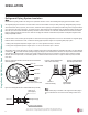
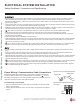
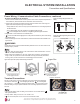
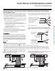
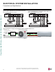
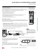
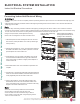
Table Of Contents

49
Electrical System Installation
Due to our policy of continuous product innovation, some specifications may change without notification.
©LG Electronics U.S.A., Inc., Englewood Cliffs, NJ. All rights reserved. “LG” is a registered trademark of LG Corp.
ELECTRICAL SYSTEM INSTALLATION
Controller Options
Single Zone High Efficiency Standard Wall Mount systems include a wireless handheld remote controller
(Model No. AKB74955602), but optional LG-suppled wired controllers are available. See “Functions, Controls,
Options” in the Engineering Manual, or contact an LG representative for more information.
Wireless Handheld Remote Controller features:
• Display Panel: Displays operation conditions.
• On / Off Button: Turns system operation on and off.
• Mode Button: Selects the operation mode: Cooling, Heating, Auto, Dry (Dehumidification), or Fan.
• Temp Up / Down Buttons: Adjusts the desired room temperature in the different modes.
• Fan Speed Button: Sets desired fan speed.
• Reset: Initializes the handheld remote control settings.
Figure 80: PZCWRC1 LG Wired Remote Extension Cable.
Verify the connectors are properly inserted.
C/BOX Cable (Plug type)
Extension cable
To Indoor Unit
CN-REMO
Terminal
TEMP
FAN
SPEED
OPER
MODE
Figure 81: Wired Controller Connections on the Indoor Unit Terminal
Block.
Wired Controller Connections
Optional controllers (see the Single Zone High Efficiency Standard Wall Mount Engineering Manual, or con-
tact an LG representative for more information) can connect to the Single Zone High Efficiency Standard Wall
Mount indoor unit in one of two different ways.
1. LG Wired Remote Extension Cable with Molex plug (PZCWRC1; sold separately) that connects to the
CN-REMO terminal on the indoor unit PCB.
2. Field-supplied controller cable that connects to the indoor unit terminal block (must be at least UL2547 or
UL1007, and at least FT-6 rated if local electric and building codes require plenum cable usage). Com-
munication cable from indoor unit to remote controller(s) is to be 22 AWG, 3-conductor, twisted, stranded,
unshielded. Wiring must comply with all applicable local and national codes.
Indoor Unit Terminal Block
1(L1 ) 2 (L2)
GND
3
GRN /
YLW
BR
BL
RD
CN-REMO
CN-CC
Controller Options
Display
Screen
Button
*
*
*
RESET
Figure 82: Example of a
Wireless Handheld Remote
Controller. Buttons will differ
depending on model type.
Dry Contact
A Dry Contact can also be connected to the High Efficiency indoor
unit using the CN-CC connection on the indoor unit PCB. The Dry
Contact DC is shipped with a specific connector that is used to
connect to the indoor unit.
Central Controller
Additionally, Single Zone High Efficiency systems can be connected
to a central controller if a PI-485 VNet Accessory is installed in the
outdoor unit. See the Central Controller manual for wiring specifica-
tions.
:KHQXVLQJ¿HOGVXSSOLHGFRQWUROOHU
cable, make sure to connect the yellow
to yellow (communications wire), red to
red (12V power wire), and black to black
(ground wire) terminals from the remote
controller to the indoor unit terminal
blocks.