
Installation Manual
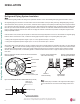
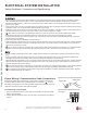
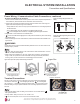
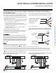
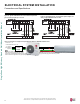
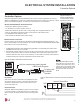
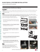
Table Of Contents

50
6LQJOH=RQH+LJK(ႈFLHQF\6WDQGDUG:DOO0RXQW,QVWDOODWLRQ0DQXDO
Due to our policy of continuous product innovation, some specifications may change without notification.
©LG Electronics U.S.A., Inc., Englewood Cliffs, NJ. All rights reserved. “LG” is a registered trademark of LG Corp.
ELECTRICAL SYSTEM INSTALLATION
Connecting Indoor Unit Electrical Wiring
• Verify that main power to the unit is completely off before proceeding with these steps as there is a risk of electrical shock, bodily injury, and /
or death.
• Follow all safety and warning information outlined at the beginning and throughout this manual. Failure to do so will cause electrical shock,
bodily injury, and / or death.
1. The bottom panel must have already been removed. If it hasn’t
been removed, unsnap the bottom cover at its top left and right
sides (Location 1).
2. Unsnap each of the three (3) or four (4) small C-hooks located in
the middle of the bottom cover (Location 2). Number of C-hooks
present depends on model of indoor unit.
3. Lift the three (3) to four (4) hinges on the bottom cover up and
out of the channels molded to the left, right, and middle of the
indoor unit (Location 3). Number of hinges present depends on
model of indoor unit.
4. Set aside the bottom cover to re-install after all procedures are
complete.
5. Terminal block is located at the front bottom-right—hand side of the
indoor unit. To access the terminals, unscrew the metal control cover
screw (if applicable), and raise the metal control cover.
6. Using a JIS screwdriver, connect the cable terminals to the
terminal block. Ensure wire color and terminal number of the
indoor unit matches those of the outdoor unit. Refer to the wiring
diagram on the inside of the bottom cover.
• Each wire must be securely attached to the terminal block.
• Ground cable must be longer than the other wires.
• Secure the cable onto the control board using a cable tie.
• Use a conduit to protect the cable / refrigerant piping from the
indoor unit to the outdoor unit.
• Follow all safety and warning information outlined at the beginning and throughout this manual. Failure to do so will cause unit failure.
• Connect the communication / connection (power) cable to the indoor unit by matching the terminals on the outdoor unit control board. Verify
the color of the wires at the outdoor unit, along with the terminal numbers, match those for the indoor unit.
• Images are representative; actual appearance will vary.
• Refer to the circuit diagram on the indoor unit bottom cover.
Figure 83: Steps to Removing
the Bottom Cover.
3
3
3
Figure 84: Removing the Bottom
Cover (Appearances Will Vary De-
pending on Indoor Unit Model).
Cover
1(L1) 2(L2) 3
Communication /
Connection
(Power) Cable
Figure 85: Location of the Indoor Unit
Terminal Block.
Figure 86: Terminal Cover Down. Figure 87: Terminal Cover Up.
Indoor Unit Electrical Connections