ENGLISH FRANÇAIS ESPAÑOL INSTALLATION MANUAL AIR CONDITIONER • Please read this installation manual completely before installing the product. • Installation work must be performed in accordance with the national wiring standards by authorized personnel only. • Please retain this installation manual for future reference after reading it thoroughly. TYPE : WALL MOUNTED (LSN/LSU-HSV2/HV2) P/NO : MFL59506804 www.lge.
Air Conditioner Installation Manual CONTENTS Installation Requirements Safety Precautions............................4 Introduction ........................................7 Symbols used in this Manual..........7 Installation ..........................................8 Installation Parts ..............................8 Installation Tools...............................8 Installation Map................................9 Select the best Location ..............
Wall Mounted Mini-Split System� Single Zone� INSTALLATION INSTRUCTIONS This air conditioning system meets strict safety and operating standards. As the installer or service person, it is an important part of your job to install or service the system so it operates safely and efficiently. WARNING • Refer to local code for all wiring size. • Installation or repairs made by unqualified persons can result in hazards to you and others.
Safety Precautions Safety Precautions To prevent the injury of the user or other people and property damage, the following instructions must be followed. ■ Be sure to read before installing the air conditioner. ■ Be sure to observe the cautions specified here as they include important items related to safety. ■ Incorrect operation due to ignoring instruction will cause harm or damage. The seriousness is classified by the following indications.
Safety Precautions Do not install the product at a place that there is concern of falling down. • Otherwise, it may result in personal injury. Use caution when unpacking and installing. • Sharp edges may cause injury. Do not share the outlet with other appliances. • It will cause an electric shock or a fire due to heat generation. Take care so that the power cord may not be pulled during operation. • Otherwise, it may cause a fire or electrical shock.
Safety Precautions ■ Installation Install the drain hose to ensure that drain can be securely done. • Otherwise, it may cause water leakage. Always inspect gas leakage after the installation and repair of product. • Otherwise, it may cause the failure of product. Install the product so that the noise or hot wind from the outdoor unit may not cause any damage to the neighbors. • Otherwise, it may cause dispute with the neighbors. Keep level parallel in installing the product.
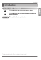
Introduction Introduction Symbols used in this Manual This symbol alerts you to hazards that may cause harm to the air conditioner. NOTICE This symbol indicates special notes. The figure of product can be different according to the type of model. Installation Manual 7 ENGLISH This symbol alerts you to the risk of electric shock.
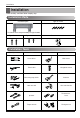
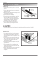
Installation Installation Read carefully, and then follow step by step. Installation Parts Installation plate Type "A" screw The feature can be changed according to a type of model.
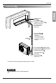
Installation Installation Map Bend the pipe as closely on the wall as possible, but be careful that it doesn't break. Vinyl tape (Wide) Saddle • Apply after carrying out a drainage test. • To carry out the drainage test, remove the air filters and pour water into the heat exchanger. Gas side piping (Optional Parts) Liquid side piping (Optional Parts) Additional drain pipe Vinyl tape (Narrow) Drain Hose Connecting cable (Optional Parts) - The feature can be changed according a type of model.
Installation Select the best Location Indoor unit 1. There should not be any heat or steam near the unit. More than 10cm(3.9in) More than 20cm(7.9in) 2. Select a place where there are no obstacles around of the unit. 3. Make sure that condensation drainage can be conveniently routed away. 4. Do not install near a doorway. 5. Ensure that the interval between a wall and the left (or right) of the unit is more than 10cm(3.9in).
Indoor unit Fixing Installation Plate The wall you select should be strong and solid enough to prevent vibration Installation Plate Type "A" Screws Chassis Hook 2. Measure the wall and mark the centerline. It is also important to use caution concerning the location of the installation plate. Routing of the wiring to power outlets is through the walls typically. Drilling the hole through the wall for piping connections must be done safely. Place a level on raised tab Unit Outline 442(17.4) 442(17.
Installation Flaring Work Main cause for gas leakage is due to defect of flaring work. Carry out correct flaring work in the following procedure. Cut the pipes and the cable. 1. Use the piping kit accessory or the pipes purchased locally. 2. Measure the distance between the indoor and the outdoor unit. Copper pipe Slanted Uneven Rough 90° 3. Cut the pipes a little longer than measured distance. 4. Cut the cable 1.5m(59.1 in) longer than the pipe length. Pipe Burrs removal Reamer 1.
Installation Check 1. Compare the flared work with the figure by. Smooth all round Inside is shiny without scratches 2. If a flared section is defective, cut it off and do flaring work again. = Improper flaring = Inclined Surface Cracked Uneven damaged thickness Connecting the Piping Indoor unit 1. Pull the screw cap at the bottom of the indoor unit 2. Remove the chassis cover from the unit by loosing 2 screws Chassis cover Indoor unit back side view 3. Pull back the tubing holder. 4.
Installation Installation Information. For right piping. Follow the instruction below. Good case • Press on the tubing cover and unfold the tubing to downward slowly. And then bend to the left side slowly. Bad case • Following bending case from right to left directly may cause damage to the tubing.
Installation Installation of Indoor Unit Installation plate 2. Unlock the tubing holder from the chassis and mount between the chassis and installation plate in order to separate the bottom side of the indoor unit from the wall Tubing Holder Piping 1.
Installation 3. Tape the tubing pipe, drain hose and the connection cable. Be sure that the drain hose is located at the lowest side of the bundle. Locating at the upper side can cause overflow from the drain pan through the inside of the unit. If the drain hose is routed inside the room insulate the hose with an insulation material* so that dripping from sweating (condensation) will not damage furniture or floors.
Installation Wrap the insulation material around the connecting portion. Insulation material Indoor unit pipe Connection pipe 2. Wrap the area which accommodates the rear piping housing section with vinyl tape. Wrap with vinyl tape Vinyl tape (wide) Connecting cable Pipe 3. Bundle the piping and drain hose together by wrapping them with vinyl tape sufficient enough to cover where they fit into the rear piping housing section.
Installation Outdoor unit 1. Remove the tubing cover from the unit by loosening the screw. Tubing cover 2. Align the center of the pipings and sufficiently tighten the flare nut by hand. 3. Finally, tighten the flare nut with torque wrench until the wrench clicks. • When tightening the flare nut with torque wrench, ensure the direction for tightening follows the arrow on the wrench. Outside diameter mm inch Ø6.35 1/4 Ø9.52 3/8 Ø12.7 1/2 Ø15.88 5/8 Ø19.
Installation Connecting the Cables Indoor • The circuit diagram is a subject to change without notice. • The earth wire should be longer than the common wires. • When installing, refer to the circuit diagram on the chassis cover. • Connect the wires firmly so that they may not be pulled out easily. • Connect the wires according to color codes, referring to the wiring diagram. Provide a circuit breaker between power source and the outdoor unit as shown below.
Installation Outdoor 1. Remove the cover control from the unit by loosening the screw. Connect the wires to the terminals on the control board individually as the following. Terminal block Over 5mm (0.2") 2. Secure the cable onto the control board with the holder (clamper). 3. Refix the cover control to the original position with the screw. Connecting cable Wiring Diagram Power supply cord Conduit panel Tubing cover 208/230 VAC NOTICE 1. Separately wire power supply cord and connecting cable. 2.
Installation ◼ For strand wiring (1) Cut the wire end with a wire cutter or wirecutting pliers, then strip the insulation to expose the strand wiring about 10mm(3/8in). (2) Using a screwdriver, remove the terminal screw(s) on the terminal plate. (3) Using a round terminal fastener or pliers, securely clamp each stripped wire end with a round terminal. (4) Position the round terminal wire, and replace and tighten the terminal screw using a screwdriver.
Installation Checking the Drainage To check the drainage. 1. Pour a glass of water on the evaporator. 2. Ensure the water flows through the drain hose of the indoor unit without any leakage and goes out the drain exit. Connecting area drain hose Leakage checking Drain pan Drain hose Leakage checking Drain piping 1. The drain hose should point downward for easy drain flow. Downward slope 2. Do not make drain piping like the following.
Installation Forming the Piping Seal small openings around pipings with a gum type sealant. 1. Tape the piping, drain hose and connecting cable from down to up. 2. Secure the tapped piping along the exterior wall using saddle or equivalent. Connecting cable (Conduit) Saddle Pipings Taping Drain hose Trap is required to prevent water from entering into electrical parts. In cases where the Outdoor unit is installed above the Indoor unit perform the following.
Installation Air Purging The air and moisture remaining in the refrigerant system have undesirable effects as indicated below. 1. Pressure in the system rises. 2. Operating current rises. 3. Cooling(or heating) efficiency drops. 4. Moisture in the refrigerant circuit may freeze and block capillary tubing. 5. Water may lead to corrosion of parts in the refrigeration system. Therefore, after evacuating the system, take a leak test for the piping and tubing between the indoor and outdoor unit.
Installation Soap water method Liquid side Gas side 2-way valve (Close) Evacuation Cap 1. Connect the charge hose end described in the preceding steps to the vacuum pump to evacuate the tubing and indoor unit. Confirm the "Lo" knob of the pressure Gauge is open. Then, run the vacuum pump. The operation time for evacuation varies with tubing length and capacity of the pump. The following table shows the time required for evacuation.
Installation Test Running 1. Check that all tubing and wiring are properly connected. 2. Check that the gas and liquid side service valves are fully open. Prepare remote controller 1. Remove the battery cover by pulling it according to the arrow direction. 2. Insert new batteries making sure that the (+) and (–) of battery are installed correctly. 3. Reattach the cover by pushing it back into position. NOTICE • Use 2 AAA(1.5volt) batteries. Do not use rechargeable batteries.
Installation Settlement of outdoor unit Bolt Tubing connection Intake temperature Evaluation of the performance Operate the unit for 15~20 minutes, then check the system refrigerant charge: 1. Measure the pressure of the gas side service valve. 2. Measure the air temperature from inlet and outlet of air conditiioner. 3. Ensure the difference between the inlet and outlet temperature is more than 8°C(46.4°F). 4.
Installation Installation guide at the seaside 1. Air conditioners should not be installed in areas where corrosive gases, such as acid or alkaline gas, are produced. 2. Do not install the product where it could be exposed to sea wind (salty wind) directly. It can result corrosion on the product. Corrosion, particularly on the condenser and evaporator fins, could cause product malfunction or inefficient performance. 3.
Installation Piping Length and Elevation Pipe Size 9k, 12k mm inch mm inch Standard Length m(ft) Ø9.52 3/8 Ø6.35 1/4 7.5(25) GAS LIQUID Max. Elevation B m(ft) Min Length A m(ft) Max. Additional Length Refrigerant (g/m) A m(ft) (after 12.5 m) 10(33) 2(6.6) 20(66) Indoor unit Outdoor unit A B 20 A Outdoor unit Indoor unit B Capacity is based on standard length and maximum allowable length is on the basis of reliability. Additional refrigerant must be charged after 12.
Air Conditioner
LG Customer Information Center 888-865-3026 888-865-3026 1-888-LG-Canada CANADA Register your product Online! LGEUS LG Electronics, Air conditioning Division 1000 Sylvan Ave., Englewood Cliffs, NJ 07632 www.lge.com LGECI LG Electronics Canada Inc. 550 Matheson Blvd. East, Mississauga, Ontario, L4Z 4G3 After reading this manual, keep it in a place easily accessible to the user for future reference.