
Wall Mounted Installation Manual


20
Multi F Standard Wall-Mounted Indoor Unit
Due to our policy of continuous product innovation, some specifications may change without notification.
©LG Electronics U.S.A., Inc., Englewood Cliffs, NJ. All rights reserved. “LG” is a registered trademark of LG Corp.
MA
X
MUL
TI
F
MUL
TI
F
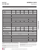
GENERAL INSTALLATION GUIDELINES
WARNING
• Mounting hardware must be securely installed to prevent the chas-
sis falling from its installation location. There is risk of personnel
injury or property damage from falling equipment.
• When choosing a location for the wall mount plate, be sure to take
into consideration routing of wiring for power outlets within the wall.
Touching wiring can cause serious bodily injury, or death.
• Installation work must be performed by trained personnel and in
accordance with all local or other applicable codes. There is risk of
injury to personnel from incorrect installation.
Note:
• Ensure the unit is properly installed. Incorrectly installed units can
result in degraded performance or an inoperative unit/system.
• Use a level indicator to ensure the installation plate and chassis
are installed on a level plane.
• If the unit is installed near a body of water, certain components
are at risk of being corroded. Appropriate anti-corrosion methods
should be taken for the unit and all components.
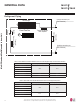
Install Wall-Mounted IDU Chassis
Mounting the Installation Plate
The mounting wall should be strong and solid enough to protect the
unit from vibration. It should securely hold the installation plate and
the weight of the chassis.
1. Determine the installation location.
2. Refer to Figure 3 or Figure 4 for the appropriate mounting
diagram.
3. Mount the installation plate on the wall using the Type “A” screws.
If mounting the unit on concrete, consider using anchor bolts.
Use a level to ensure the plate is level.
4. Always mount the installation plate horizontally. Measure the wall
and mark the centerline using thread and a level.
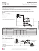
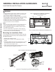
Figure 3: Installation Plate for LMN078HVT, LSN090HSV4,
LSN120HSV4, and LMN158HVT Units.
Installation Plate
Frame
Hooks
Type "A" Screws
Figure 4: Installation Plate for LSN180HSV4 and LMN248HVT Units.
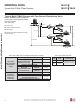
Figure 5: Installation Plate Attaching Screw Placement.
Ø2-3/4 inches
Ø2-3/4 inches
2-23/32 inches
2-7/32 inches
Right rear
piping
Left rear
piping
Installation Plate
Measuring Tape
Measuring Tape Hanger
Place a level on raised tab
Unit Outline
8-5/32 inches
4-1/8 inches
18-1/8 inches 22-7/16 inches
Ø2-9/16
5-3/16 3-11/16
Right rear piping
Left rear piping
Place a level on raised tab
Unit Outline
8-1/2
6-7/8
17-3/8 17-3/8
5
Ø2-9/16
A-Type
B-Type