
Engineering Manual

MULTI
F
MAX
MULTI
F
Power Wiring / Communications Cable Guidelines
Installation and Best Layout Practices
DUCT (HIGH STATIC) INDOOR UNITS
Connecting the Power Wiring and Communications Cable
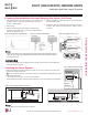
1. To access the terminal block, first unscrew the cover from the control box.
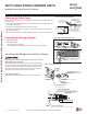
2. Insert the power wiring / communications cable from the outdoor unit or branch
distribution unit (Multi F MAX systems only) through the sides of the indoor unit
and control box. Pass the wiring through the designated access holes to prevent
damage. To prevent electromagnetic interference and product malfunction, leave
a space between the power wiring and communications cable outside of the
indoor unit.
3. Connect each wire to its appropriate terminal on the indoor unit control board.
Verify that the color and terminal numbers from the outdoor unit or branch
distribution unit (Multi F MAX systems only) wiring match the color and terminal
numbers on the indoor unit.
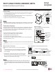
4. Secure the power wiring / communications cable with the cable
restraint.
5. Screw the steel clamp to the inside of the control panel.
• Place the wiring / cables in the clamp and tighten the plastic
clamp to an open surface of the control panel.
• When clamping, do not apply force to the wiring connections.
• Neatly arrange the wiring, do not catch the wiring in the electric
box cover, and ensure the cover firmly closes.
6. Fill in any gaps around the wiring access holes with sealant to
prevent foreign particles from entering the indoor unit.
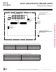
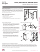
Figure 144:Accessing the Indoor Unit Terminal Block.
A
Control Box
Terminal Block
Control Box Cover
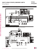
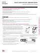
1(L1)2(L2) 3
Power Wiring Connections
Lock nut
Conduit
mounting
plate
Conduit
Indoor Unit Terminal Block
1(L1 )2(L2)
GND
3
Outdoor Unit Terminal Block or
Branch Distribution Unit Terminal Block
(Multi F MAX Systems Only)
GND
GRN
/
YLW
BR
BL
RD
3 or S
Figure 145:Indoor Unit to Outdoor Unit / Branch Distribution Unit (Multi F
MAX systems only) Power Wiring / Communications Cable
Connections.
• Follow manufacturer’s circuit diagrams in the technical manuals.
• Confirm power source specifications.
• Confirm that the electrical capacity is sufficient.
• Starting current must be maintained ±10 percent of the rated current marked on the outdoor unit name plate.
• Confirm cable thickness specifications.
• It is recommended that a circuit breaker is installed, especially if conditions could become wet or moist.
• Include a disconnect in the power wiring system, add an air gap contact separation of at least 1/8 inch in each active (phase) conductor.
• Loose wiring may cause unit to malfunction, overheat, and catch fire, resulting in severe injury or death.
Note:
• Terminal screws may become loose during transport. Properly tighten the terminal connections during installation.
A voltage drop may cause the following problems:
• Magnetic switch vibration, fuse breaks, or disturbance to the normal function of an overload protection device.
• Compressor will not receive the proper starting current.
DUCT (HIGH STATIC) | 107
Ceiling-Concealed Duct (High Static)
Due to our policy of continuous product innovation, some specications may change without notication.
©LG Electronics U.S.A., Inc., Englewood Cliffs, NJ. All rights reserved. “LG” is a registered trademark of LG Corp.