
Engineering Manual
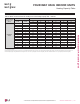


Refrigerant Flow Diagram
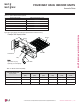
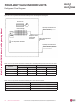
Figure 227: Four-way Vertical-Horizontal Air Handling Indoor Unit Refrigerant Flow Diagram.
FOUR-WAY VAHU INDOOR UNITS
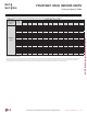
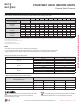
Table 105: Four-way Vertical-Horizontal Air Handling Indoor Unit Refrigerant Pipe Sizes and Connection Sizes.
Model No.
Piping Size Connection Port Size
Liquid (inch) Vapor (inch) Liquid (inch) Vapor (inch)
LVN180HV4 1/4 1/2 3/8 5/8
LVN240HV4 1/4 1/2 3/8 5/8
LVN360HV4 3/8 5/8 3/8 5/8
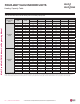
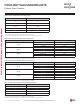
Table 106: Four-way Vertical-Horizontal Air-Handling Indoor Unit Thermistor Details.
Description (Based on Cooling Mode) PCB Connector
Indoor Air Temperature Thermistor CN-ROOM
Evaporator Inlet Temperature Thermistor CN-PIPE/IN
Evaporator Outlet Temperature Thermistor CN-PIPE/OUT
Scirocco Fan
Heat Exchanger
Heating
Ev. Temperature Thermistor
Evaporator Outlet
Temperature
Thermistor
Cooling
M
Vapor Pipe Connection Port
(Flare Connection)
Indoor Air Temperature
Thermistor
Liquid Pipe Connection Port
(Flare Connection)
Due to our policy of continuous product innovation, some specications may change without notication.
©LG Electronics U.S.A., Inc., Englewood Cliffs, NJ. All rights reserved. “LG” is a registered trademark of LG Corp.
170 | VERTICAL-HORIZONTAL
Multi F and Multi F MAX Indoor Unit Engineering Manual
MULTI
F
MAX
MULTI
F