SINGLE ZONE EXTENDED PIPING WALL MOUNTED ENGINEERING MANUAL 2 Tons 2-1/2 and 2-3/4 Tons LS243HLV3 LS303HLV3, LS363HLV3
PROPRIETARY DATA NOTICE This document, as well as all reports, illustrations, data, information, and other materials are the property of LG Electronics U.S.A., Inc., and are disclosed by LG Electronics U.S.A., Inc. only in confidence. This document is for design purposes only. A summary list of safety precautions is on page 3. For more technical materials such as submittals, catalogs, installation, owner’s, and service manuals, visit www.lghvac.com. For continual product development, LG Electronics U.S.
TABLE OF CONTENTS Unit Nomenclature .........................................................................................................................................................................................................4 LG Air Conditioner Technical Solution (LATS) .........................................................................................................................................................5-6 Product Data .........................................................
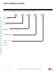
UNIT NOMENCLATURE Single Zone Wall Mount Indoor and Outdoor Units Single Zone Extended Piping Wall Mounted Engineering Manual LS N 243 HLV Family LS = Wall Mounted Type N = Indoor Wall Mount Unit U = Outdoor Heat Pump Unit Capacity (Mbh) 243 = 22 303 = 30 363 = 33 Indoor/Outdoor Product HLV - Extended Piping Generation or Revision 1 = First 2 = Second 3 = Third 4 = Fourth 4 | INTRODUCTION 'XH WR RXU SROLF\ RI FRQWLQXRXV SURGXFW LQQRYDWLRQ VRPH VSHFL¿FDWLRQV PD\ FKDQJH ZLWKRXW QRWL¿FDWLRQ
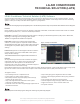
LG AIR CONDITIONER TECHNICAL SOLUTION (LATS) LG Air Conditioner Technical Solution (LATS) Software A properly designed and installed refrigerant piping system is critical to the optimal performance of LG air-conditioning systems. To assist engineers, LG offers, free of charge, LG Air Conditioner Technical Solution (LATS) software—a total design solution for LG air conditioning systems. Contact your LG Rep for the best software program for your application.
LG AIR CONDITIONER TECHNICAL SOLUTION (LATS) LATS Generates a Complete Project Report Single Zone Extended Piping Wall Mounted Engineering Manual LATS software also generates a report containing project design parameters, cooling and heating design data, system component performance, and capacity data.
PRODUCT DATA Mechanical Specifications on page 8 General Data on page 9 Electrical Data on page 11 Functions, Controls, Options on page 12 Outdoor Unit Dimensions on page 13 Outdoor Unit Center of Gravity / Corner Weight on page 14 Indoor Unit Dimensions on page 15 Acoustic Data on page 17 Refrigerant Flow Diagram on page 21 Indoor Unit Wiring Diagram on page 22 Outdoor Unit Wiring Diagram on page 23 Electrical Connections on page 24 Air Flow, Static Pressure, and Temperature Distribution on page 28
MECHANICAL SPECIFICATIONS Extended Piping Wall Mounted System Single Zone Extended Piping Wall Mounted Engineering Manual General LG Single Zone Wall Mounted Extended Piping systems are comprised of a single outdoor unit connected to a single indoor unit with a single refrigerant circuit. These single zone systems can operate in either cooling or heating mode. These systems are capable of changing mode within a maximum time of three (3) minutes to ensure temperature can be properly maintained.
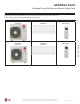
GENERAL DATA Extended Piping Wall Mounted System Pairing Table The following tables show the available outdoor and indoor units, along with the factory provided controllers. Table 1: Single Zone Wall Mounted Extended Piping System Pairing Table Outdoor Unit Model Indoor Unit Model Controller LSU243HLV3 LSN243HLV3 AKB74955602 LSU303HLV3 LSU363HLV3 LSN303HLV3 LSN363HLV3 AKB74955602 Product Data 'XH WR RXU SROLF\ RI FRQWLQXRXV SURGXFW LQQRYDWLRQ VRPH VSHFL¿FDWLRQV PD\ FKDQJH ZLWKRXW QRWL¿FDWLRQ ©
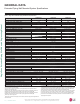
GENERAL DATA Single Zone Extended Piping Wall Mounted Engineering Manual ([WHQGHG 3LSLQJ :DOO 0RXQWHG 6\VWHP 6SHFL¿FDWLRQV Table 2: 6LQJOH =RQH ([WHQGHG 3LSLQJ :DOO 0RXQWHG 6SHFL¿FDWLRQV LS243HLV3 LS303HLV3 LS363HLV3 System (Model) (Indoor Unit / Outdoor Unit) (LSN243HLV3/LSU243HLV3) (LSN303HLV3/LSU303HLV3) (LSN363HLV3/LSU363HLV3) 3,070 ~ 22,000 ~ 30,000 3,070 ~ 30,000 ~ 34,000 3,070 ~ 33,000 ~ 34,000 Cooling Capacity1 (Min/Rated/Max) (Btu/h) 1.69 2.66 3.
ELECTRICAL DATA Extended Piping Wall Mounted Systems Table 3: 208-230V, 60Hz, 1-Phase Single-Zone Extended Piping Wall-Mounted Electrical Data. Nominal Tons 2 2-1/2 2-3/4 Unit Model Hertz Voltage Voltage Range Number (Min. to Max.) MCA LS243HLV3 LS303HLV3 LS363HLV3 19.0 23.0 23.0 60 Voltage tolerance is ±10%. Maximum allowable voltage unbalance is 2%. MCA = Minimum Circuit Ampacity. 208 - 230 187 - 253 MOP Compressor Qty. 30 30 30 1 1 1 Compressor Motor RLA Cooling Heating 14.41 15.1 15.1 14.
LS243HLV3 1 5 Steps 6 Steps ¥ ¥ 6/6/6 ¥ ¥ ¥ ¥ ¥ X X X X ¥ ¥ ¥ ¥ ¥ ¥ ¥ o ¥ ¥ +RXU ¥ o o ¥ ¥ ¥ ¥ Number Display On / Off ¥ ¥ Controllers Functions Air Purifying $LUÀRZ Table 4: Indoor Units—Functions, Controls and Options.
Air Outlet 13-7/32 (336) 6-17/32 (166) 37-13/32 (950) Ø22-1/8 (562) 24-13/32 (620) Control Box 15-11/32 (390) 14-3/16 (360) 1-9/16 (40) Power / Comm. Cable Holes Vapor Pipe Conn. (Flare Joint) Liquid Pipe Conn. (Flare Joint) 3-5/32 (80) 2-17/32 (64) 32-3/4 (832) 1-1/32 (26) 15-7/16 (392) Drain Hole 5-Ø13/16 (20) 15/16 (24) Sump Heater 'XH WR RXU SROLF\ RI FRQWLQXRXV SURGXFW LQQRYDWLRQ VRPH VSHFL¿FDWLRQV PD\ FKDQJH ZLWKRXW QRWL¿FDWLRQ © /* (OHFWURQLFV 8 6 $ ,QF (QJOHZRRG &OLIIV 1- $
OUTDOOR UNIT CENTER OF GRAVITY / CORNER WEIGHT Single Zone Extended Piping Wall Mounted Engineering Manual Figure 4: Center of Gravity and Corner Weight Dimensions Diagram. d D A e c C B b a Table 5: Center of Gravity and Corner Weight Dimensions. Model 14 | Weight (lb.) Shipping Net Center of Gravity (inch) a b c Leg (inch) d e Corner Weight (lb.) A B C D LSU243HLV3 147.7 135.4 23-7/32 12-19/32 5-29/32 24-13/32 14-3/16 18.6 24.2 49.1 43.5 LSU303HLV3, LSU363HLV3 160.3 147.
2-3/8 (60) 1/8(3) x 1/4(6) 1/4(6) x 1/8(3) 1-1/4 (31) 2-7/16 (61.5) 1-3/32 (50.2) 1-1/16 (26.2) 15/32 (12) Refrigerant, Drain Pipe and Cable Routing Hole 2-13/32(61) 1-9/32(32.7) 2-5/8 (67) 7/16 (11) 5-31/32 (152) 1-7/16(33.5) 'XH WR RXU SROLF\ RI FRQWLQXRXV SURGXFW LQQRYDWLRQ VRPH VSHFL¿FDWLRQV PD\ FKDQJH ZLWKRXW QRWL¿FDWLRQ © /* (OHFWURQLFV 8 6 $ ,QF (QJOHZRRG &OLIIV 1- $OO ULJKWV UHVHUYHG ³/* ´ LV D UHJLVWHUHG WUDGHPDUN RI /* &RUS 12° 47° Cooling 22° Heating 57° Up & Down *
2-3/8 (60) 1/8(3) x 1/4(6) 1/4(6) x 1/8(3) 1-1/4 (31) 2-7/16 (61.5) 1-3/32 (50.2) 1-1/16 (26.2) 15/32 (12) [2Air 23/32 Ou (6 tlet 9)] Hol e Refrigerant, Drain Pipe and Cable Routing Hole 2-13/32(61) 1-7/16(33.5) Decoration Cover [40-19/32 (1031)] Air Intake Hole 47-1/4 (1200) 'XH WR RXU SROLF\ RI FRQWLQXRXV SURGXFW LQQRYDWLRQ VRPH VSHFL¿FDWLRQV PD\ FKDQJH ZLWKRXW QRWL¿FDWLRQ © /* (OHFWURQLFV 8 6 $ ,QF (QJOHZRRG &OLIIV 1- $OO ULJKWV UHVHUYHG ³/* ´ LV D UHJLVWHUHG WUDGHPDUN RI /* &RUS
INDOOR UNIT ACOUSTIC DATA Extended Piping Wall Mounted Systems Indoor Unit Sound Pressure Measurement / Sound Pressure Levels Figure 5: Extended Piping Wall Mounted Indoor Unit Sound Level Measurement Location. • • • • • Measurements are taken 3.3 feet (1 m) away from the front of the unit. Sound pressure levels are measured in dB(A) with a tolerance of ±1. Reference acoustic pressure 0dB=20μPa. Data is valid at nominal operation conditions. Operating conditions are assumed to be standard.
INDOOR UNIT ACOUSTIC DATA Extended Piping Wall Mounted Systems LSN303HLV3 and LSN363HLV3 Sound Pressure Levels Figure 7: Sound Pressure Levels for LSN303HLV3 Indoor Units.
OUTDOOR UNIT ACOUSTIC DATA Extended Piping Wall Mounted Systems Outdoor Unit Sound Pressure Measurement / Sound Pressure Levels • Measurements are taken 3.3 feet (1 m) away from the front of the unit. • Sound pressure levels are measured in dB(A) with a tolerance of ±1. • Data is valid at nominal operation conditions. Operating conditions are assumed to be standard. • Reference acoustic pressure 0dB=20μPa.
OUTDOOR UNIT ACOUSTIC DATA Extended Piping Wall Mounted Systems LSU303HLV3 and LSU363HLV3 Sound Pressure Levels Figure 11: Sound Pressure Levels for LSU303HLV3 Outdoor Units.
REFRIGERANT FLOW DIAGRAMS LSU/LSN243HLV3, LSU/LSN303HLV3, LSU/LSN363HLV3 Refrigerant Flow Diagram for Extended Piping Wall Mounted Systems Indoor Unit Outdoor Unit Field Pipin g (Copper Tubing) 3-W ay Valve Liquid Side EEV M TH1 TH4 Heat Exchanger (Evaporator) Heat Exchanger (Condenser) M TH2 3-W ay Valve TH3 Reversing Valve Field Pipin g (Copper Tubing) TH5 Vapor Side Product Data TH6 Accumulator : Cooling : Heating Compressor Table 8: LSN / LSU243-303-363HLV3 Thermistor Details.
INDOOR UNIT WIRING DIAGRAM LSN243HLV3, LSN303HLV3, LSN363HLV3 Single Zone Extended Piping Wall Mounted Engineering Manual Wiring Diagram for Extended Piping Wall Mounted Indoor Units 01-2020 22 | PRODUCT DATA 'XH WR RXU SROLF\ RI FRQWLQXRXV SURGXFW LQQRYDWLRQ VRPH VSHFL¿FDWLRQV PD\ FKDQJH ZLWKRXW QRWL¿FDWLRQ © /* (OHFWURQLFV 8 6 $ ,QF (QJOHZRRG &OLIIV 1- $OO ULJKWV UHVHUYHG ³/* ´ LV D UHJLVWHUHG WUDGHPDUN RI /* &RUS
OUTDOOR UNIT WIRING DIAGRAM LSU243HLV3, LSU303HLV3, LSU363HLV3 Wiring Diagram for Extended Piping Wall Mounted Outdoor Units Product Data 01-2020 'XH WR RXU SROLF\ RI FRQWLQXRXV SURGXFW LQQRYDWLRQ VRPH VSHFL¿FDWLRQV PD\ FKDQJH ZLWKRXW QRWL¿FDWLRQ © /* (OHFWURQLFV 8 6 $ ,QF (QJOHZRRG &OLIIV 1- $OO ULJKWV UHVHUYHG ³/* ´ LV D UHJLVWHUHG WUDGHPDUN RI /* &RUS PRODUCT DATA | 23
ELECTRICAL CONNECTIONS Single Zone Extended Piping Wall Mounted Engineering Manual General Power Wiring / Communications Cable Guidelines • • • • • • Follow manufacturer’s circuit diagrams displayed on the inside of the control box cover. Confirm power source specifications. Properly ground the outdoor unit and the indoor unit per National Electrical Code (NEC) and local codes. Connect the wiring firmly so that the wires cannot be easily pulled out. Confirm that the electrical capacity is sufficient.
ELECTRICAL CONNECTIONS Communication / Connection (Power) Cable Specifications from Outdoor Unit to Indoor Unit Figure 16: Typical Single Zone Outdoor Unit to Indoor Unit Wiring and All power wiring and communication cable installation must be performed by trained service providers working in accordance with local, state, and National Electrical Code (NEC) / UL / ETL federal regulations related to electrical equipment and wiring, and following the manufacturer product diagrams, requirements, and instructi
ELECTRICAL CONNECTIONS Figure 23: Schematic of a Single Zone System When the Wiring is GREATER THAN 130 Feet. Power Flow: L ĺ N Communication Flow: Comm ĺ N Single Zone Extended Piping Wall Mounted Engineering Manual 1(L1) (Power, L) 2(L2) (Neutral, N) G (Ground) Power Supply At Least Two (2) Inches Diagram is an example of communication and power cables when the wiring is GREATER THAN 130 feet. Terminals may be labeled differently depending on the model.
ELECTRICAL CONNECTIONS Wired Controller Placement Figure 24: Proper Location for the Wired Controller. Wired controllers include a sensor to detect room temperature. To maintain comfort levels in the conditioned space, the wired controller must be installed in a location away from direct sunlight, high humidity, and where it could be directly exposed to cold air.
AIR FLOW, STATIC PRESSURE, AND TEMPERATURE DISTRIBUTION Single Zone Extended Piping Wall Mounted Engineering Manual Table 10: Extended Piping Wall Mounted Outdoor Unit Air Flow Rate and Static Pressure. Model Air Flow Rate (CFM) Static Pressure (in. WG) LSU243HLV3 2,119 0.0409 LSU303HLV3, LSU363HLV3 2,295 0.0480 LSN243HLV3 Cooling Air Velocity [m/s (ft./s)] 0.5(1.6) Temperature [°C (°F)] 2(6.6) 1(3.3) 0.3(1) m 2 ft. 6.6 1 3.3 0 0 m 26(79) 28(82) 22(72) 18(64) 2 ft. 6.6 1 3.
AIR FLOW, STATIC PRESSURE, AND TEMPERATURE DISTRIBUTION LSN243HLV3, continued. Heating Air Velocity [m/s (ft./s)] Temperature [°C (°F)] 0.5(1.6) 0.3(1) 2(6.6) 1(3.3) m 2 ft. 6.6 1 3.3 0 0 24(75) 30(86) 32(90) 26(79) 22(72) m 10 8 6 4 2 0 m 10 8 6 4 2 0 ft. 32.8 26.2 19.7 13.1 6.6 0 ft. 32.8 26.2 19.7 13.1 6.6 0 m 2 ft. 6.6 1 3.3 0 0 Side View Discharge $QJOH Û )URP WKH IORRU Vertical Louver : Center Fan Speed : Power ) Air Velocity [m/s (ft./s)] m ft.
AIR FLOW, STATIC PRESSURE, AND TEMPERATURE DISTRIBUTION LSN303HLV3 Cooling Air Velocity [m/s (ft./s)] Single Zone Extended Piping Wall Mounted Engineering Manual 0.3(1) Temperature [°C (°F)] 0.5(1.6) 1(3.3) 2(6.6) m 2 ft. 6.6 1 3.3 0 0 26(79) 28(82) 22(72) 18(64) m 10 8 6 4 2 0 m 10 8 6 4 2 0 ft. 3 2 .8 26.2 19.7 13.1 6 .6 0 ft. 3 2 .8 26.2 19.7 1 3 .1 6.6 0 m 2 ft. 6.6 1 3.
AIR FLOW, STATIC PRESSURE, AND TEMPERATURE DISTRIBUTION LSN303HLV3, continued. Heating Air Velocity [m/s (ft./s)] Temperature [°C (°F)] 0.5(1.6) 0.3(1) 2(6.6) 1(3.3) m 2 ft. 6.6 1 3.3 0 0 28(82) 30(86) 26(79) 24(75) m 10 8 6 4 2 0 m 10 8 6 4 2 0 ft. 32.8 26.2 19.7 13.1 6.6 0 ft. 32.8 26.2 19.7 13.1 6.6 0 m 2 ft. 6.6 1 3.3 0 0 Side View Discharge $QJOH Û )URP WKH IORRU Vertical Louver : Center Fan Speed : Power ) Air Velocity [m/s (ft./s)] m ft. 5 16.
AIR FLOW, STATIC PRESSURE, AND TEMPERATURE DISTRIBUTION LSN363HLV3 Cooling Air Velocity [m/s (ft./s)] Single Zone Extended Piping Wall Mounted Engineering Manual 0.3(1) 0.5(1.6) Temperature [°C (°F)] 1(3.3) 2(6.6) m 2 ft. 6.6 1 3.3 0 0 26(79) 28(82) 22(72) 18(64) m 10 8 6 4 2 0 m 10 8 6 4 2 0 ft. 32.8 26.2 19.7 13.1 6.6 0 ft. 32.8 26.2 19.7 13.1 6.6 0 m 2 ft. 6.6 1 3.
AIR FLOW, STATIC PRESSURE, AND TEMPERATURE DISTRIBUTION LSN363HLV3, continued. Heating Air Velocity [m/s (ft./s)] Temperature [°C (°F)] 0.5(1.6) 0.3(1) 2(6.6) 1(3.3) m 2 ft. 6.6 1 3.3 0 0 28(82) 30(86) 26(79) 24(75) m 10 8 6 4 2 0 m 10 8 6 4 2 0 ft. 32.8 26.2 19.7 13.1 6.6 0 ft. 32.8 26.2 19.7 13.1 6.6 0 m 2 ft. 6.6 1 3.3 0 0 Side View Discharge $QJOH Û )URP WKH IORRU Vertical Louver : Center Fan Speed : Power ) Air Velocity [m/s (ft./s)] m ft. 5 16.
PERFORMANCE DATA Cooling Capacity Data on page 35 Maximum Cooling Capacity Data on page 37 Heating Capacity Data on page 39 Maximum Heating Capacity on page 41 Equipment Selection Procedure on page 43
PERFORMANCE DATA Cooling Capacity LS243HLV3, LS303HLV3 Cooling Capacity Table for LS243HLV3 (LSU243HLV3 + LSN243HLV3) Table 11: LSN243HLV3 / LSU243HLV3 Cooling Capacities. Outdoor Air Temp. (°F DB) 13.32 13.07 13.16 13.29 13.47 14.46 14.69 15.25 15.82 16.39 16.96 17.52 18.09 18.66 18.49 18.32 18.15 17.98 17.81 17.64 17.47 17.01 16.56 16.10 15.53 15.18 10.35 10.20 10.29 10.44 10.62 11.41 11.59 12.03 12.48 12.93 13.38 13.82 14.27 14.72 14.59 14.45 14.32 14.19 14.05 13.92 13.79 13.43 13.06 12.70 12.25 11.
PERFORMANCE DATA Cooling Capacity LS363HLV3 Cooling Capacity Table for LS363HLV3 (LSU363HLV3 + LSN363HLV3) Table 13: LSN363HLV3 / LSU363HLV3 Cooling Capacities. Single Zone Extended Piping Wall Mounted Engineering Manual Outdoor Air Temp. (°F DB) 0 5 7 10 14 23 25 30 35 40 45 50 55 60 65 70 75 80 85 90 95 100 105 110 115 118 64 / 53 TC SHC PI 19.98 19.60 19.73 19.94 20.21 21.69 22.03 22.88 23.73 24.58 25.44 26.29 27.14 27.99 27.74 27.48 27.23 26.97 26.72 26.46 26.21 25.52 24.84 24.15 23.29 22.77 15.
PERFORMANCE DATA Maximum Cooling Capacity LS243HLV3, LS303HLV3 Max. Cooling Capacity Table for LS243HLV3 (LSU243HLV3 + LSN243HLV3) Table 14: LSN243HLV3 / LSU243HLV3 Maximum Cooling Capacities. Outdoor Air Temp. (°F DB) 13.43 13.49 13.59 13.73 13.92 12.60 12.59 12.57 12.55 12.53 12.51 12.49 12.46 12.44 12.24 12.03 11.82 11.61 11.40 11.19 10.99 10.29 9.59 8.89 8.28 7.91 11.52 11.78 11.85 11.96 12.11 10.96 10.95 10.93 10.90 10.88 10.86 10.83 10.81 10.78 10.61 10.44 10.26 10.09 9.92 9.75 9.57 8.93 8.29 7.
PERFORMANCE DATA Maximum Cooling Capacity LS363HLV3 Max. Cooling Capacity Table for LS363HLV3 (LSU363HLV3 + LSN363HLV3) Table 16: LSN363HLV3 / LSU363HLV3 Maximum Cooling Capacities. Single Zone Extended Piping Wall Mounted Engineering Manual Outdoor Air Temp. (°F DB) 0 5 7 10 14 23 25 30 35 40 45 50 55 60 65 70 75 80 85 90 95 100 105 110 115 118 64 / 53 TC SHC PI 17.43 17.49 17.59 17.73 17.92 16.60 16.59 16.57 16.55 16.53 16.51 16.48 16.46 16.44 16.24 16.03 15.82 15.61 15.40 15.19 14.99 14.29 13.59 12.
PERFORMANCE DATA Heating Capacity LS243HLV3, LS303HLV3 Heating Capacity Table for LS243HLV3 (LSU243HLV3 + LSN243HLV3) Table 17: LSN243HLV3 / LSU243HLV3 Heating Capacities. Outdoor Air Temp. °F DB °F WB -4 -1 0 5 9 14 15 17 23 30 38 40 43 50 53 57 61 65 TC 60 13.26 14.44 14.62 15.28 15.95 16.45 16.56 16.79 18.41 22.07 25.33 26.14 27.36 27.63 28.26 28.86 29.41 29.82 PI TC 1.39 1.52 1.54 1.59 1.64 1.66 1.68 1.71 1.77 1.92 2.04 2.07 2.12 2.14 2.16 2.21 2.24 2.27 12.86 14.00 14.18 14.81 15.47 15.95 16.
PERFORMANCE DATA Heating Capacity LS363HLV3 Heating Capacity Table for LS363HLV3 (LSU363HLV3 + LSN363HLV3) Table 19: LSN363HLV3 / LSU363HLV3 Heating Capacities. Outdoor Air Temp. Single Zone Extended Piping Wall Mounted Engineering Manual °F DB °F WB -3 0 1 6 10 16 17 19 24 32 41 43 47 53 59 64 70 75 -4 -1 0 5 9 14 15 17 23 30 38 40 43 50 53 57 61 65 Indoor Air Temperature (°F DB) TC 17.96 19.55 19.80 20.68 21.59 22.27 22.43 22.73 24.93 29.88 34.29 35.39 37.04 37.41 38.26 39.08 39.82 40.
PERFORMANCE DATA Maximum Heating Capacity LS243HLV3, LS303HLV3 Maximum Heating Capacity Table for LS243HLV3 (LSU243HLV3 + LSN243HLV3) Table 20: LSN243HLV3 / LSU243HLV3 Maximum Heating Capacities. Outdoor Air Temp. °F DB °F WB -4 -1 0 5 9 14 15 17 23 30 38 40 43 50 53 57 61 65 TC 60 21.44 22.66 23.16 25.71 27.05 28.30 28.62 28.97 30.44 32.78 35.41 36.00 37.19 38.16 38.64 38.95 39.08 38.98 PI TC 2.87 2.90 2.90 3.00 3.03 3.06 3.05 3.08 3.15 3.17 3.07 3.07 3.00 3.05 2.99 2.92 2.79 2.55 21.32 22.48 22.
PERFORMANCE DATA Maximum Heating Capacity LS363HLV3 Maximum Heating Capacity Table for LS363HLV3 (LSU363HLV3 + LSN363HLV3) Table 22: LSN363HLV3 / LSU363HLV3 Maximum Heating Capacities. Single Zone Extended Piping Wall Mounted Engineering Manual Outdoor Air Temp. °F DB °F WB -3 0 1 6 10 16 17 19 24 32 41 43 47 53 59 64 70 75 -4 -1 0 5 9 14 15 17 23 30 38 40 43 50 53 57 61 65 Indoor Air Temperature (°F DB) TC 27.18 28.72 29.35 32.59 34.30 35.88 36.28 36.72 37.30 38.22 39.25 39.48 39.96 41.00 41.52 41.
EQUIPMENT SELECTION PROCEDURE Correction Factors Cooling / Heating Correction Factors For Single Zone Extended Piping Wall Mounted systems, calculate the equivalent length of the liquid line from the outdoor unit to the indoor unit. Also, determine the elevation difference of the indoor unit above or below the outdoor unit. Find the corresponding cooling or heating capacity correction factors as shown below.
EQUIPMENT SELECTION PROCEDURE Correction Factors Single Zone Extended Piping Wall Mounted Engineering Manual Check the Indoor and Outdoor Unit Selection(s) Compare the corrected cooling and heating capacities to the load calculations. Is each capacity sufficient for the zone it serves? For the indoor unit, the corrected capacity must be at least equal to the total of the cooling design load (plus ventilation load, if applicable) for the space served by the indoor unit.
APPLICATION GUIDELINES Placement Considerations on page 46 Installing Outdoor Units Indoors on page 51 Refrigerant Piping Design on page 54
PLACEMENT CONSIDERATIONS Indoor Unit Selecting the Best Location for the Indoor Unit Figure 25: Extended Piping Indoor Unit Clearance Requirements. Single Zone Extended Piping Wall Mounted Engineering Manual Follow required best practices when choosing an indoor location for the single zone indoor unit. Do’s • Minimum clearance of indoor unit from the top of the unit to the ceiling must be greater than 8 inches.
PLACEMENT CONSIDERATIONS Outdoor Unit Selecting the Best Location for the Outdoor Unit • DANGER Do not install the unit in an area where combustible gas will generate, flow, stagnate, or leak. These conditions can cause a fire, resulting in bodily injury or death. • Do not install the unit in a location where acidic solution and spray (sulfur) are often used as it can cause bodily injury or death.
PLACEMENT CONSIDERATIONS Outdoor Unit Planning for Snow and Ice, continued. CAUTION Single Zone Extended Piping Wall Mounted Engineering Manual When deciding on a location to place the outdoor unit, be sure to choose an area where run-off from defrost will not accumulate and freeze on sidewalks or driveways, which will create unsafe conditions. Properly install and insulate any drain hoses to prevent the hose from freezing, cracking, leaking, and causing unsafe conditions from frozen condensate.
PLACEMENT CONSIDERATIONS Outdoor Unit Oceanside Applications Figure 29: Oceanside Placement Using Windbreak. Use of a Windbreak to Shield from Sea Wind Windbreak Ocean winds will cause corrosion, particularly on the condenser and HYDSRUDWRU ¿QV ZKLFK LQ WXUQ FRXOG FDXVH SURGXFW PDOIXQFWLRQ RU LQHI¿FLHQW SHUIRUPDQFH • • • • • Sea wind Additional anti-corrosion treatment will need to be applied to the outdoor unit at oceanside locations. Figure 30: Placement Using Building as Shield.
PLACEMENT CONSIDERATIONS Outdoor Unit Single Zone Extended Piping Wall Mounted Engineering Manual Minimum Clearance Requirements for Single Zone Extended Piping Systems Proper clearance for the outdoor unit coil is critical for proper unit operation. When installing the outdoor unit, consider service, inlet and outlet and minimum allowable space requirements as illustrated in the diagrams below. Specific clearance requirements in the diagram below are for Single Zone Extended Piping Wall Mounted systems.
PLACEMENT CONSIDERATIONS Installing Outdoor Units Indoors Installing Outdoor Units Indoors Benefits of Installing Outdoor Units Indoors • • • • • Shelters the outdoor unit from direct exposure to prevailing winds that decrease the heating capability of the outdoor unit. Protects equipment from freezing precipitation and / or potential ice build-up that could hinder unit operation. Maintains coil heat transfer efficiency by reducing the number of and shortening the cycle time for defrost operation.
PLACEMENT CONSIDERATIONS Installing Outdoor Units Indoors Single Zone Extended Piping Wall Mounted Engineering Manual Provide a means to drain the condensate generated during heating mode and defrost cycle in addition to rainwater that infiltrates the inlet louver enclosed area. • Install a field-provided drain pan under the outdoor units and provide a path to a nearby floor drain.
PLACEMENT CONSIDERATIONS Installing Outdoor Units Indoors Open Rate by Louver Radian Figure 34: Open Rate by Louver Radian Formula. W h ho H Application Guidelines ho = h * COS Total Area (A) = H * W Number of Open Spaces (N) = (Number of Louvers - 1) Effective Area (Af) = ho * W * N Louver Open Rate (n) = Af / A Af = A * n Side View Effective Cross Section Area Front View Confirming Air Flow Rate / Total Opening Rate Figure 35: Example of Installing Outdoor Unit Indoors.
REFRIGERANT PIPING DESIGN Design Guideline Summary Device Connection Limitations Single Zone Wall Mounted Extended Piping Engineering Manual Single-zone systems consist of one outdoor unit and one indoor unit. One of the most critical elements of a single zone system is the refrigerant piping. The table below lists pipe length limits that must be followed in the design of a Single Zone Extended Piping Wall Mounted refrigerant pipe system. Refer to the figure for maximum length and elevation of piping.
20001747 ISO 9001: 2008 LG ELECTRONICS INC. LG Electronics, U.S.A., Inc. Air Conditioning Technologies 4300 North Point Parkway Alpharetta, Georgia 30022 www.lghvac.