
Installation Guide

59
Electrical System Installation
Due to our policy of continuous product innovation, some specifications may change without notification.
©LG Electronics U.S.A., Inc., Englewood Cliffs, NJ. All rights reserved. “LG” is a registered trademark of LG Corp.
ELECTRICAL SYSTEM INSTALLATION
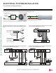
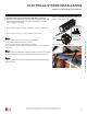
Do not install power wiring to the outdoor unit
and the communication / connection (power) cable
to the indoor unit in the same conduit. Use separate
conduits. Communication problems will occur.
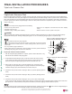
Figure 112: Example of Conduit.
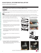
Connecting Outdoor Unit Wiring, continued.
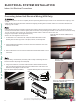
6. Using a JIS screwdriver, connect wires as shown at right. See
also indoor unit wiring diagram found on its bottom cover, and
outdoor unit wiring diagram on the inside of its chassis cover.
• Each wire must be individually and securely attached to each
terminal.
Loose, damaged, or cracked wires will cause electric shock, bodily
injury and / or death.
Loose wires can cause the wiring to burn out, damaging the outdoor
unit.
• Secure wiring / cables with cable ties.
• Pay attention to the location / connection of the ground cable.
• Maintain a minimum of 1/4 inches of wire length from terminal block
to cable bundle.
7. When finished, reattach the piping / control box cover or con-
trol box cover (depends on model) to the outdoor unit with the
screws.
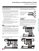
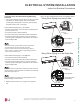
Figure 113: HEV2 and HXV Outdoor Unit Conduit
Holes / Access Points.
LSU090, 120HEV2 and
LSU090,120HXV
LSU180, 240HEV2
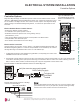
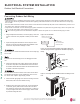
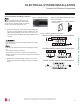
Figure 114: Outdoor Unit Electrical Connections.
LSU180-240HEV2 Outdoor Unit Terminal Block
LSU090-120HEV2 Outdoor Unit Terminal Block
LSU090-120HXV Outdoor Unit Terminal Block
Outdoor Unit Electrical Connections