
Engineering Manual


35
Installation Manual
Due to our policy of continuous product innovation, some specifications may change without notification.
©LG Electronics U.S.A., Inc., Englewood Cliffs, NJ. All rights reserved. “LG” is a registered trademark of LG Corp.
INSTALLATION
WARNING
Securely install threaded rod hangars (bolts) and hardware to
prevent the
chassis falling from its installation location.
• There is risk of personnel injury from falling equipment.
Installation work must be performed by trained personnel and in
accordance with all local or other applicable codes.
• There is risk of injury to personnel from incorrect installation.
Note:
• Ensure the unit is properly installed. Incorrectly installed units can
malfunction
resulting in degraded performance or an inoperative unit/system.
• Securely install threaded rod hangars (bolts) and hardware to prevent
the chassis falling from its installation location. There is risk of equip-
ment orproperty damage from falling equipment.
• Use a level indicator to ensure the chassis is installed on a level plane.
Roughing In the Indoor Unit
1. Determine the installation location. Ensure the location has enough space to allow necessary duct connections and maintenance access.
2. Securely install the four field-provided threaded rod hangars to the overhead support locations.
3. Hang the chassis from the four field-supplied threaded rod hangars. Refer to the threaded rod hangar details in Figure 8.
4. Use a level to ensure the chassis is level and securely tighten the mounting nuts.
5. If local code requires an auxiliary drain pan under the unit, install a field-provided auxiliary drain pan.
6. Connect ductwork to the unit as necessary.
Roughing-In Wall-Mounted Zone Controllers
Note:
• It may be necessary to use a handy box that is sized in metric units, depending on the controller model. Check with your LG representa-
tive to verify which size of handy box is needed for the zone controller in question.
• Use only LG-supplied communications cable. Using field-supplied cable may result in communications problems between the zone con-
troller and the indoor unit.
• DO NOT cut the quick-connect plugs off or adjust the length of the cable.
• Keep the communications cable away from high voltage wires and electromagnetic field (EMF) producing equipment.
• Do not route power wiring and communications cables in the same conduit.
• Maintain the minimum distance required between the communications cable and power wiring. The minimum required space between the
two is dependent on the voltage of the power wiring. Refer to the appropriate Multi V Outdoor Unit Engineering Manual for
minimum distance specifications.
1. Proper indoor unit operation depends on the location of the room sensor. A good location will protect the zone controller from direct
sunlight and external local sources of water vapor, and heated or cooled air. If no mounting height was specified by the building de-
signer, place the handy box approximately fifty-five (55) inches above the finished floor.
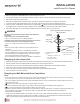
Install Ducted IDU Chassis
Figure 8: Typical Threaded Rod Hanger and
Attaching Hardware
The following parts are field
supplied:
• Hanging bolt - W-3/8″ or 1/2″
• Nut - W-3/8″ or M10
• Spring washer - M10
Included with the indoor unit:
• Flat washer - M10
Flat washer for M10
(accessory)
Flat washer for M10
(accessory)
Hanging bolt
(W3/8 or M10)
Nut
(W3/8 or M10)
Nut
(W3/8 or M10)
Spring washer
(M10)
3. Remove the protective cardboard/Styrofoam
®
top sheet and place to the side.
4. The walls and top panels are not attached to the bottom of the box. Lift the carton by the flaps and remove the box walls and top.
5. Remove the moisture barrier plastic bonnet.
6. Check the unit nameplate data and model number. Verify the unit voltage, and capacities are correct before proceeding.
7. Locate and retain the piping/condensate accessory kit located in the bottom of the box under the refrigerant pipe stubs.
8. Using two people, carefully lift the unit and inspect for freight damage. DO NOT lift by the refrigerant piping or drain pipe stub. Lift by
the hangar brackets or chassis frame only. If damage is found, repack the unit as it was received in the original container.
9. If the unit is undamaged, remove and retain the installation manual. It is located under or on top of the unit.