ENGLISH FRANÇAIS ESPAÑOL INSTALLATION MANUAL AIR CONDITIONER Please read this installation manual completely before installing the product. Installation work must be performed in accordance with the national wiring standards by authorized personnel only. Please retain this installation manual for future reference after reading it thoroughly. Vertical Air Handling Unit MFL67206513 Rev.01_061319 www.lghvac.com www.lg.com Copyright © 2016 - 2019 LG Electronics Inc. All Rights Reserved.
IMPORTANT! Please read this instruction sheet completely before installing the product. This air conditioning system meets strict safety and operating standards. As the installer or service person, it is an important part of your job to install or service the system so it operates safely and efficiently. ! WARNING • Installation or repairs made by unqualified persons can result in hazards to you and others.
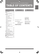
Vertical Air Handling Unit Installation Manual Installation Requirements Safety Precautions...............................4 Features ................................................6 Duct Connection Dimensions .............7 Installation ............................................8 Selection of the best location .............8 Upflow Installation ..............................9 Downflow Installation........................10 Horizontal-Right Installation .............12 Duct work .........................
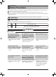
Safety Precautions Safety Precautions To prevent injury to the user or other people and property damage, the following instructions must be followed. n Be sure to read before installing the air conditioner. n Be sure to observe the cautions specified here as they include important items related to safety. n Incorrect operation due to ignoring instruction will cause harm or damage. The seriousness is classified by the following indications.
Safety Precautions Do not install the product on a defective installation stand. Be sure the installation area does not deteriorate with age. • There is risk of fire, electric shock, explosion, or injury. • It may cause injury, accident, or damage to the product. • If the base collapses, the air conditioner could fall with it, causing property damage, product failure, and personal injury. Use a vacuum pump or Inert (nitrogen) gas when doing leakage test or air purge.
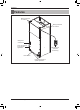
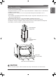
Features Features Wiring knockouts for conduit Wiring knockouts for conduit Refrigerant connections FAN SPEED TEMP OPER MODE Drain connections for horizontal application Wired Remote Controller (Accessory) Filter access Drain connections for upflow application 6 Vertical Air Handling Unit
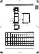
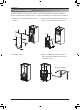
Features ENGLISH Duct Connection Dimensions Drain connections for upflow application Refrigerant connections Drain connections for horizontal application Air filter cover (Unit: inch(mm)) Wiring Knock out Dimensions ODU Single Zone Multi Zone Capacity (kBtu/h) A B C I D E F G J Refrigerant Connections Pipe size H Power Commu Liquid nication Height Width Depth Gas 18 24 36 48-5/8 18 (1 236) (457) 21-1/4 1-9/16 17-1/2 (540) (40) (445) 20 (530
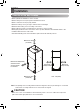
Installation Installation Selection of the best location • Where optimum air distribution can be ensured. • Where nothing blocks air passage and install the duct work. • Where condensate can be properly drained. • Where the ceiling is strong enough to bear the indoor unit weight. • Where the false ceiling is not noticeably on an incline. • Where sufficient clearance for maintenance and service can be ensured. • Where piping between indoor and outdoor units is possible within the allowable limit.
Installation • Position unit for plenum installation. • The plenum should be secured in order to support the installation of adapter callers accommodate the installation of any duct work. • Seal all duct work according to local codes to prevent air leakage. Ensure that filter access is unobstructed. • The air handler support platform should be sturdy enough to support the cabinet plus any accessory components including filter box.
Installation Downflow Installation Downflow installation requires various changes to the air handling unit from original configuration. There are additional kits required in order to convert the air handling unit to the downflow configuration. 1) Please remove the panels and Brackets from the unit. A 2) Please remove the thermistor from a coil. Also remove a coil and Drain pan from the unit D Deletion E B F C 3) Rotate the cabinet. 4) Please assemble the downflow bracket as below.
Installation 6) The brackets are required to be reattached. 7) Reinstall the new panel. Room C Eva In E Eva Out New F A Installation Manual 11 ENGLISH 5) Reinsert the coil back to the cabinet.
Installation Horizontal-Right Installation Downflow installation requires various changes to the air handling unit from original configuration. There are additional kits required in order to convert the air handling unit to the downflow configuration. 1) Please remove the panels and Brackets from the unit. A 2) Please remove the thermistor from a coil. Also remove a coil and Drain pan from the unit. D G E B F C 3) Rotate the drain pan. 4) Reinstall brackets and panel.
Installation • Over 10 screws should be used for joining supply duct with the unit. • To prevent vibration transmission, exploit flexible connectors between duct and the unit. It is mandatory that the flexible connector between unit and duct at discharge connection should be made off heat resistive material when electric heater is installed. • Duct work must be insulated and covered with vapor barrier when routed through unconditioned space.
Installation Horizontal-left Installation • It is particular that the units should not be installed in such a manner that the access panels facing up or down • It should be confirmed that the installation is in accordance with all relevant building codes that may necessitate installation of external condensate pan. -Set up a support for unit by locating it in or above external condensate pan.
Installation ENGLISH Combination indoor units (Multi Zone) The indoor units connectable to the outdoor unit are shown below Indoor Unit Type Vertical AHU Outdoor Unit (kBtu/h) Capacity (kBtu/h) 36 54 18 / 24 O O 36 X O 24 O O 36 X O Ceiling Concealed Duct (High Static) NOTICE : 1. The total capacity(in Btu/h unit) of connected indoor unit models represents the total sum of the figures expressed in the indoor model name. 2.
Installation Flaring work Main cause of gas leakage is defect in flaring work. Carry out correct flaring work in the following procedure. Copper tube 90° Slanted Uneven Rough 1) Cut the pipes n Use the accessory piping kit or the pipes purchased locally. n Measure the distance between the indoor and the outdoor unit. n Cut the pipes a little longer than measured distance. n Cut the cable 1.5 m(4.9 ft) longer than the pipe length.
Gas side piping Installation ENGLISH Connection of piping - Indoor, Outdoor, BD Unit Align the center of the piping and sufficiently tighten the flare nut by hand. ODU Capacity (kBtu/h) Liquid Single Zone Multi Zone BD Unit PMBD3620 PMBD3630 PMBD3640 PMBD3641 18 24 36 42 48 18 24 36 Indoor unit tubing Refrigerant Connections Pipe size Flare nut Pipes Gas Open-end wrench (fixed) Flare nut 3/8 (Ø 9.52) 5/8 (Ø 15.88) Torque Wrench Connection pipe Indoor unit tubing 1/4 (Ø 6.35) 1/4 (Ø 6.
Installation ! CAUTION Always blow nitrogen into pipe which is brazed. Always use a non-oxidizing brazing material for brazing the parts and do not use flux. If not, oxidized film can cause clogging or damage to the compressor unit and flux can harm the copper piping or refrigerant oil.
Installation ENGLISH Insulation Insulate the joint and tubes completely. Thermal insullaton : All thermal insulation must comply with local requirement. Union for liquid pipe Refrigerant pipe and thermal insulator (Local supply) Hose crip for thermal insulator (Local supply) Thermal insulator for refrigerant pipe(Local supply) Union for gas pipe Thermal insulator for refrigerant pipe (Local supply) Thermal insulator for piping(Local supply) Overlap with thermal insulator for piping.
Installation Condensate Drain • The drainage performance has to be optimized by installing both primary and secondary drain lines along with properly sized condensate traps in order to prevent property damage. • Care should be taken to avoid the blocking of filter access panel while connecting condensate drain lines. The primary and secondary condensate traps has to be primed after connecting to the drain pan.
Installation GRADIENT OF UNIT AND DRAIN PIPING • 5/24 inch(5 mm) or thicker formed thermal insulator shall always be provided for the drain pipe. Thermal insulator (Field supply) Drainage pipe (Field supply) Unit Make sure to be closed. Drainage hole Applied U-Trap Dimension A ≥ 2-3/4 inch (70 mm) B ≥ 2C C ≥ 2 x SP SP = External Pressure C (in.wc) Ex) External Pressure = 0.4 in.wc(10 mmAq) A A ≥ 2-9/16 inch(70 mm) B ≥ 1-7/12 inch(40 mm) C ≥ 19/24 inch(20 mm) 3/4 inch(19.
Installation Wiring Connection Connect the wires to the terminals on the control board individually according to the outdoor unit connection. Ensure that the color of the wires of outdoor unit and the terminal No. are the same as those of indoor unit respectively.
Installation ENGLISH Lock nut Conduit mounting plate 1/2 inch(21.3 mm) Conduit Thermostat cable Wired remote controller cable Connecting cable 2. Install conduit to the wiring knockouts. Connect connecting / wired remote controller cable or Thermostat cable to terminal block through the wiring knockouts. NOTICE : 1.
Remote controller installation Remote controller installation ※Remote controller is provided as an accessory. Please fix tightly using provided screw after placing remote controller setup board on the place where you like to setup. - Please set it up not to bend because poor setup could take place if setup board bends. Please set up remote controller board fit to the reclamation box if there is a reclamation box. Can set up Wired remote controller cable into three directions.
Remote controller installation Please connect indoor unit and remote controller using connection cable. Connecting Cable Signal 12v GND YELLOW RED BLACK Remote Controller PCB FAN SPEED 12 V Red Signal Yellow GND Black TEMP OPER MODE Please use extension cable if the distance between wired remote controller and indoor unit is more than 10 m(32-4/5 ft).
Remote controller installation Wired remote controller installation Since the room temperature sensor is in the remote controller, the remote controller box should be installed in a place away from direct sunlight, high humidity and direct supply of cold air to maintain proper space temperature. Install the remote controller about 5 ft(1.5 m) above the floor in an area with good air circulation at an average temperature.
3rd Party Thermostat ENGLISH 3rd Party Thermostat Indoor Unit Side W2 Y W G Thermostat R C ODU NOTE h Can not use LG wired remote control and 3rd party thermostat at the same time. h When connecting the thermostat, please refer to the thermostat manual.
Internal Electric Heater(Accessory) Internal Electric Heater(Accessory) Feature (Example: 5 kW) Bi metal Bracket Heater Coil Terminal Block Relay Heater Cable * Note: Image shown above may vary depends on model capacity. Available heater in model Capacity (kBtu/h (RT)) 18(1.5) 24(2.0) 36(3.0) 42(3.5) 48(4.
DIP Switch Setting of Indoor unit PCB Function SW1 Communication Description N/A (Default) SW2 Cycle N/A (Default) SW3 Group Control Selection of Master or Slave SW4 Dry Contact Mode Selection of Dry Contact Mode Setting Off - Setting On - Default Off - - Off Master Slave Off Wired/Wireless remote controller Selection of Manual or Auto operation Mode Auto Off SW5 Installation Fan continuous operation Continuous operation Removall - Off SW6 Heater linkage Selection of Heating W
Product Data Product Data Minimum airflow by heater capacity (Unit : CFM) Capacity (kBtu/h (RT)) 18(1.5) 24(2.0) 36(3.0) 42(3.5) 48(4.0) ! 3 480 480 800 1 000 1 000 5 480 480 800 1 000 1 000 Heater Capacity (kW) 8 10 480 480 480 480 800 800 1 000 1 000 1 000 1 000 CAUTION Do not use less than minimum airflow. There is risk of fire or damage to the product.
US CANADA Please call the installing contractor of your product, as warranty service will be provided by them.