OWNER’S MANUAL AIR CONDITIONER Please read this manual carefully before operating your set and retain it for future reference. TYPE:WINDOW MODEL:LW701 HR P/NO:0)/ www.lgappliances.
Window-Type Air Conditioner Owner’s Manual TABLE OF CONTENTS Safety Precautions..........................3 FOR YOUR RECORDS Write the model and serial numbers here: Before Operation .............................7 Model # Serial # Introduction ....................................8 You can find them on a label on the side of each unit. Dealer's Name Electrical Safety ..............................
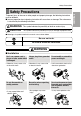
Safety Precautions Safety Precautions WARNING This symbol indicates the possibility of death or serious injury. CAUTION This symbol indicates the possibility of injury or damage to properties only. ■ Meanings of symbols used in this manual are as shown below. Be sure not to do. Be sure to follow the instruction. WARNING ■ Installation Don’t use a power cord, a plug or a loose socket which is damaged. • Otherwise, it may cause a fire or electrical shock. Always plug into a grounded outlet.
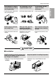
Safety Precautions ■ Operation Do not place heavy object on the power cord and take care so that the cord should not be pressed. Do not share the outlet with other appliances. • There is danger of fire or electric shock. • It will cause electric shock or fire due to heat generation. Do not place the power cord near a heater. • It may cause fire and electric shock. Do not allow water to run into electric parts. • It will cause failure of machine or electric shock.
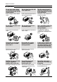
Safety Precautions Do not operate or stop the unit by inserting or pulling out the power plug. Hold the plug by the head when taking it out. • It may cause electric shock and damage. • It will cause electric shock or fire. When gas leaks, open the window for ventilation before operating the unit. • Otherwise, it may cause explosion, and a fire. Do not operate with wet hands or in damp environment. • It will cause electric shock. Never touch the metal parts of the unit when removing the filter.
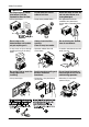
3AFETY 0RECAUTIONS /PERATION $O NOT PUT A PET OR HOUSE PLANT WHERE IT WILL BE EXPOSED TO DIRECT AIR FLOW s )T MAY CAUSE INJURY $O NOT STEP ON THE INDOOR OUTDOOR UNIT AND DO NOT PUT ANYTHING ON IT s )T MAY CAUSE AN INJURY THROUGH DROPPING OF THE UNIT OR FALLING DOWN "E CAUTIOUS NOT TO TOUCH THE SHARP EDGES WHEN INSTALLING s )T MAY CAUSE INJURY 2OOM !IR #ONDITIONER $O NOT BLOCK THE INLET OR OUTLET OF AIR FLOW 5SE A SOFT CLOTH TO CLEAN $O NOT USE WAX THINNER OR A STRONG DETERGENT s )T MAY CAU
Before Operation Before Operation 1. 2. 3. 4. 5. 6. Contact an installation specialist for installation. Plug in the power plug properly. Use a dedicated circuit. Do not use an extension cord. Do not start/stop operation by plugging/unplugging the power cord. If the cord/plug is damaged, replace it with only an authorized replacement part. Usage 1. Being exposed to direct airflow for an extended period of time could be hazardous to your health.
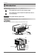
Introduction Introduction Symbols Used in this Manual This symbol alerts you to the risk of electric shock. This symbol alerts you to hazards that could cause harm to the air conditioner. NOTICE This symbol indicates special notes. Features (Appearance may vary) This appliance should be installed in accordance with the National Electric Code.
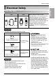
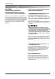
Electrical Safety Electrical Safety 115V~ 230V~ Power cord may include a current interrupter device. A test and reset button is provided on the plug case. The device should be tested on a periodic basis by first pressing the TEST button and then the RESET button. If the TEST button does not trip or if the RESET button will not stay engaged, discontinue use of the air conditioner and contact a qualified service technician. NOTICE The shape may be different according to its model.
Electrical Safety Electrical Safety IMPORTANT (PLEASE READ CAREFULLY) FOR THE USER'S PERSONAL SAFETY, THIS APPLIANCE MUST BE PROPERLY GROUNDED The power cord of this appliance is equipped with a three-prong (grounding) plug. Use this with a standard three-slot (grounding) wall power outlet to minimize the hazard of electric shock. The customer should have the wall receptacle and circuit checked by a qualified electrician to make sure the receptacle is properly grounded.
Installation How to Install the Unit 1. To prevent vibration and noise, make sure the unit is installed securely and firmly Fence Awning 3. The outside of the cabinet must extend outward for at least 11" and there should be no obstacles, such as a fence or wall, within 20" from the back of the cabinet because it will prevent heat radiation of the condenser. Restriction of outside air will greatly reduce the cooling efficiency of the air conditioner. Cooled air Heat radiation 30"~60" 2.
Installation Installation Kits Contents 2 1 5 3 6 7 4 8 12 11 10 9 NO. NAME OF PARTS Q'TY 1 2 3 4 5 6 7 8 9 10 11 12 FRAME CURTAIN SILL SUPPORT BOLT NUT SCREW(TYPE A) SCREW(TYPE B) SCREW(TYPE C) FOAM-STRIP DRAIN PIPE FRAME GUIDE WINDOW LOCKING BRACKET FOAM-PE 2 2 2 2 13 3 5 1 1 2 1 1 Suggested Tool Requirements SCREWDRIVER(+, -), RULER, KNIFE, HAMMER, PENCIL, LEVEL PREPARATION OF CHASSIS Shipping Screws 1. Remove the screws which fasten the cabinet at both sides and at the back. 2.
Installation Cabinet Installation 2. Pull the bottom window sash down behind the upper guide until it meets. Upper Guide Window stool Front Angle Fig. 1 Window Sash Upper guide Foam-pe 12 NOTICE Cabinet Frame Curtain Do not pull the window sash down so tightly that the movement of Frame Curtain is restricted. 1 Foam-pe Fig. 2 INDOOR OUTDOOR 3. Loosely assemble the sill support using the parts in Fig. 3. Sill Support Bolt 4 Fig. 3 Screw(Type A) Frame Guide 2 5 10 About 1/2" 4.
Installation 9. Attach each Frame curtain the window sash using screws (Type C).(See Fig. 6) Type C Do not drill a hole in the bottom pan. The unit is designed to operate with approximately 1/2" of water in bottom pan. 7 Fig. 6 10. Slide the unit into the cabinet.(See Fig. 7) For security purpose, reinstall screws(Type A) at cabinet's sides. Power cord Screw(Type A) Screw(Type A) Fig. 7 Foam-Strip 11.
Installation How to Use the Reversible Inlet Grille ENGLISH 1. If you want to pull out the filter upward, open the inlet grille slightly. Turn inside out the front grille. Disassemble the inlet grille from the front grille with separating the hinged part by inserting a "—" type screw-driver tip. Rotate the inlet grille 180 degrees and insert the hooks into the lower holes of front grille. Then, insert the filter. (See Fig.12, 13) Fig. 12 2.
Operating Instructions Operating Instructions Remote control The remote control and control panel will look like one of the following pictures. 4 REMOTE CONTROLLER Power 7 1 Temp 5 Fan Speed 4 5 Timer 1 3 Mode 2 Energy Saver 6 3 6 2 1. POWER BUTTON To turn the air conditioner ON, push the button. To turn the air conditioner OFF, push the button again. This button takes priority over any other buttons. 2.
......................... 21Hours 22Hours 23Hours 24Hours y battery one battery battery battery battery.
Operating Instructions Ventilation The ventilation lever must be in the CLOSE position in order to maintain the best cooling conditions. When fresh air is necessary in the room, set the ventilation lever to the OPEN position. The damper is opened and room air is drawn out. Part B CLOSE VENT OPEN NOTICE Before using the ventilation feature, position the lever, as shown. First, pull down part to horizontal line with part .
Operating Instructions How to Attach Drain Pan(Optional) In very humid weather, (and for reverse cycle models in the reverse mode) excessive condensate water removed from the air may cause some water to collect. To remove this excess water you can install the drain pan as detailed below. CABINET 1. Take the drain pan which is located in the air discharge. ENGLISH The air conditioner employs a proper drain method whereby the condensed water (moisture removed from the air) is drained to the outside. 2.
Maintenance and Service Maintenance and Service TURN THE AIR CONDITIONER OFF AND REMOVE THE PLUG FROM THE POWER OUTLET. Air Filter Cleaning he air filter should be checked at least twice a month to see if cleaning is necessary. Trapped particles in the filter will build up and block the airflow. This reduces the cooling capacity and also causes an accumulation of frost on the cooling coils. 1. Open the inlet grille upward by pulling out the bottom of the inlet grille.
Maintenance and Service Common Problems and Solutions The air conditioner is operating normally when: • You hear a pinging noise. This is caused by water being picked up by the condenser on rainy days or in highly humid conditions. This feature is designed to help remove moisture in the air and improve cooling efficiency. • You hear the thermostat click. This is caused by the compressor cycle starting and stopping. • You see water dripping from the rear of the unit.
Manual del usuario del acondicionador de aire tipo Ventana TABLA DE CONTENIDOS PARA SUS ARCHIVOS Escriba aquí el modelo y número de serie: Precauciones de Seguridad .........23 Antes de poner el equipo en funcionamiento..............................27 Modelo n°: Serie n°: Puede encontrar estos datos en la etiqueta situada en el lateral de cada unidad. Nombre del distribuidor: Fecha de compra: Introducción...................................
Precauciones de Seguridad Precauciones de Seguridad Para evitar lesiones al usuario o a otras personas y daños a la propiedad, estas instrucciones estén seguirse. ■ Una operación incorrecta por ignorar las instrucciones provocará lesiones o daños. La seriedad se clasifica por las siguientes indicaciones. Este símbolo indica la posibilidad de muerte o de seria lesión.
Precauciones de Seguridad ■ Operación No use el cable de alimentación cerca gas inflamable o materiales combustibles tales como la gasolina, benceno, disolvente, etc. • Puede ocasionar una explosión o descarga eléctrica. No ponga el cable de alimentación cerca de un calentador. • Puede ocasionar un incendio y una descarga eléctrica. No comparta el tomacorriente con otros electrodomésticos. Saque el enchufe en caso de necesidad, sosteniendo la cabeza del enchufe y no lo toque con las manos mojadas.
Precauciones de Seguridad No opere ni detenga la unidad insertando o estirando de enchufe. No dañe ni use un enchufe de alimentación no especificado. • Provocará descargas eléctricas o incendios. Sostenga el enchufe por su cabeza al sacarlo. Cuando haya un escape de gas, abra la ventana para ventilar antes de poner en marcha la unidad. • Podría ocasionar una descarga eléctrica y daños. • De lo contrario, podría ocurrir una explosión o incendio. • Provocará descargas eléctricas.
Precauciones de Seguridad Operación No ponga plantas ni animales en la trayectoria que recorrerá el aire caliente. • Podría ocasionar lesiones. No se suba a la unidad interior/exterior ni coloque objetos sobre la misma. • Puede lesionarse al caerse del aparato o al caerse los objetos que haya colocado. Tenga cuidado para no tocar los bordes puntiagudos al instalar. • Podría ocasionar lesiones. No bloquee la entrada ni la salida del flujo de aire. • Puede causar una avería en el aparato.
Antes de poner el equipo en funcionamiento Antes de poner el equipo en funcionamiento Preparación para el funcionamiento Uso 1. Estando expuesto a la circulación directa de aire durante un extenso período de tiempo podría resultar peligroso para su salud. No exponga a las personas, animales domésticos, o a las plantas a la circulación de aire durante largos períodos de tiempo. 2.
Introducción Introducción Símbolos Utilizados en Este Manual Este símbolo lo advierte de un peligro de accidente por corriente eléctrica. Este símbolo lo adiverte de un peligro que pueda causar un daño del ventliador. CONSEJO Este símbolo significa condicciones especiales. Características (aparencia puede variar) Este aparato debería instalarse de acuerdo con las normas del Código Eléctrico Nacional.
Seguraida Electrica Seguraida Electrica Datos Electricos 115V~ 230V~ CONSEJO La forma puede ser diferente según su modelo. Utilice el enchufe de la pared Standard 125V, enchufe de 3 Líneas de 15A, 125V AC Consumo de Energía Utilice un fusible de 15AMP. o un Interruptor de 15AMP. Standard 250V, enchufe de 3 Líneas de 15A, 250V AC Standard 250V, enchufe de 3 Líneas de 20A, 250V AC Utilice un fusible de 20AMP. o un Interruptor de 20AMP.
Seguraida Electrica Seguraida Electrica IMPORTANTE (FAVORLEA CON ATENCIÓN) POR LA SEGURIDAD PERSONAL DEL USUARIO, ESTE APARATO DEBE SER DEBÍDAMENTE NEUTRALIZADO. El cordón de energía de éste aparato esta equipado con tres patas(cable a tierra). Utilice éste con un enchufe de pared de tres salidas(a tierra) para minimizar el peligro de choque eléctrico. El cliente debe revisar el receptor de pared y el circuito por un electricista calificado para asegurarse que la recepción esta debidamente neutralizada.
Instalacion Instalacion Elija el major lugar Cerca Pabellón Aire frio 30"~60" Radiacion de calor Aproximamente 1/2" Over 20" Todas las ventanillas de los lados del gabinete deben mantenerse expuestas hacia afuera de la estructura. 4 Instale la unidad un poco inclinada de tal forma que la parte trasera esté ligeramente más baja que el frente(cerca de 1/2"). Esto forzará el agua del condensador hacia afuera. 5. Instale la unidad con la parte inferior cerca de 30"~60" arriba nivel de suelo.
Instalacion Contenido del Juego de Instalación 2 1 5 3 6 7 4 8 12 11 10 9 NO.
Instalación del Gabinete ), REGLA, CUCHILLO, MARTILO, LAPIZ, NIVEL CONSEJO Guía Superior Taburete de la Ventana Marco de Ventana Gabinet Panel Guía 1 Banda adhesiva Fig. 2 Interior Exterior Soporte del Alféizar 2 Tornillo 3 4. Seleccione la posición que ubicará el soporte del alféizar cerca del punto más exterior del alféizar.(Ver Fig. 4) Guía Superior Banda adhesiva 12 No hale la ventana hacia abajo tan apretadamente que el movimiento del panel guía sea restringido. 3.
Instalacion 9. Adjunte cada panel guía a cada lado de la ventana usando tornillos (Tipo C). (Ver Fig. 6) Tipo C No perfore la charola del fondo. La unidad está diseñada para operar con aproximadamente 1/2" de agua en la charola del fondo. 7 Fig. 6 10. Deslice el chasís dentro del gabinete. (Ver Fig. 7) Conrdon de Alimentacion Por razones de seguridad, re instale los tornillos(Tipo A) en los lados del gabinete. 11.
Instalacion Cómo usar la rejilla de entrada reversible 2. Pegue el panel frontal a la caja insertando los fijadores en el panel adentro los del panel de la caja. (Ver Fig. 14) Fig. 12 Fig. 13 La rejilla de entrada 3. Levante la parrilla de entrada y ajústela con tornillos Tipo A, através de la parrilla frontal. (Ver Fig. 15) 4. Si usted desea sacar el filtro por abajo, usar la rejilla de entrada reversible. (La rejilla es ya diseñada para tal manera) Fig. 14 Fig.
Instruccionnes de Funcionamiento Instruccionnes de Funcionamiento Control remoto El mando a distancia y el panel de control se parecerán a los de las siguientes imágenes. 4 CONTROL REMOTO Power 7 1 Temp 5 Fan Speed 4 5 Timer 1 3 Mode 2 Energy Saver 6 3 6 2 1. BOTÓN DE LA CORRIENTE Para ENCENDER el sistema presione el botón, y para APAGARLO presione el botón otra vez. Este botón tiene prioridad sobre todos los otros botones. 2.
.......... .......... 22Horas 23Horas 24Horas ESPAÑOL
Instruccionnes de Funcionamiento Ventilacion La palanca de ventilación deberá estar en la posición CLOSE (Cerrado) para poder mantener las mejores condiciones de enfriamiento. Cuando se necesite aire fresco en la habitación, coloque la palanca de ventilación en la posición OPEN (Abierto). El amortiguador se abre y se descarga el aire de la habitación. Part B CLOSE VENT OPEN CERRAR VENTILACION ABRIR CONSEJO Antes de usar la característica de ventilación, Part A coloque la palanca como se muestra.
Instruccionnes de Funcionamiento Como colocar la charola de purga(Opcional) El aire acondicionado utiliza un método de purga adecuado en donde el agua condensada (humedad retirada del aire) se purga al exterior. En climas demasiado húmedos (y para modelos de ciclo invertido en la modalidad de inversión) el agua condensada excesiva que se retira del aire puede ocasionar que se recolecte algo de agua. Para eliminar este exceso de agua, puede instalar una charola de purga como se detalla a continuación.
Cuidado y Mantenimiento Cuidado y Mantenimiento APAGUE EL AIRE ACONDICIONADO Y SAQUE EL ENCHUFE DEL TOMA CORRIENTE DE LA PARED. Limpleza del filtro de aire El filtro de aire deverá revisarse cuando menos dos veces al mes para vertioficar si es necesario limpiarlo. Las partículas atrapadas en el filtro podrían acumularse y bloquear el flujo de aire. Esto reduce la capacidad de enfriamiento y también ocasiona la acumulación de escarcha en los serpentines de enfriamiento. 1.
Cuidado y Mantenimiento Problemas y soluciones habituales Problema Causas posibles ■ El acondicionador de aire está desenchufado o no bien enchufado ■ El fusible está fundido / el disyuntor está interrumpido El acondicionador ■ Corte de corriente de aire no funciona para nada Qué hacer • Asegúrese que el enchufe está completamente enchufado dentro del tomacorriente • Compruebe el fusible /la caja del disyuntor y reemplace el fusible o vuelva el disyuntor a su lugar.
Garantía GARANTÍA LIMITADA DEL AIRE ACONDICIONADO LG - EE.UU. COBERTURA DE LA GARANTÍA: LG Electronics Inc. (“LG”) garantiza que reparará o sustituirá, gratuitamente, su producto si resulta defectuoso en materiales o mano de obra bajo condiciones normales de uso durante el periodo de garantía mencionado más abajo, efectivo a partir de la fecha de compra del producto original por parte del consumidor.
WARRANTY LG ROOM AIR CONDITIONER LIMITED WARRANTY - USA WHAT THIS WARRANTY COVERS: LG Electronics U.S.A., Inc. (“LG”) warrants your LG Room Air Conditioner ("product") against defect in materials or workmanship under normal household use, during the warranty period set forth below, LG will, at its option, repair or replace the product.
LG Customer Information Center 1-800-243-0000 LG ELECTRONICS,INC. 1000 Sylvan Ave.,Englewood Cliffs,NJ 07632 Register your product Online! www.lgappliances.