SERVICMANULOD:F-421()/TPW5 P/N : 3829RET006M JANUARY, 2005 MP3 PLAYER SERVICE MANUAL CAUTION BEFORE SERVICING THE UNIT, READ THE "SAFETY PRECAUTIONS" IN THIS MANUAL.
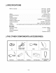
[CONTENTS] SECTION 1. GENERAL ?ESDPRECAUTIONS.....................................................1-2 ?SPECIFICATION..........................................................1-3 ?THEOTHERCOMPONENTS(ACCESSORIES).................................1-3 ?IDENTIFICATIONOFCONTROLS............................................1-4 SECTION 2. ELECTRICAL SECTION ?TROUBLESHOOTING....................................................2-1 ?INTERNALBLOCKDIAGRAMOFICs........................................2-6 ?BLOCKDIAGRAM.....
SECTION 1. GENERAL ESD PRECAUTIONS Electrostatically Sensitive Some semiconductor commonly circuits and be used to 1. called are some help devices (solid state) Electrostatically Devices (ESD) damaged easily by static electricity. Such components (ESD). Examples of typical ESD devices are integrated and semiconductor chip components. The following techniques should component damage caused by static electricity.
SPECIFICATIONS ?MemoryCapacity.............................................MF-FE421:128MB MF-FE422 : 256 MB MF-FE425 : 512MB MF-FE429 : 1GB ?Battery........................................................AAAtype(1EA) ?Dimensions(WxHxD)...........................................68.2x22.2x30.8mm ?Weight.....................................................45g(withoutbattery) ?OperatingVoltage......................................................1.5VDC ?DynamicRange.....................................
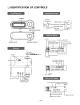
IDENTIFICATION OF CONTROLS USB In/Out Earphone connector external input terminal Battery cover Volume Sound Repeat indicator. quality file indicator Lyrics Current track number/ Total track number. effect Radio transmitter indicator 003/004:12 Love is Play/Pause Power(ON)/(OFF) REW/FF HOLD POP game.mp3 singer button and song title Battery remaining B.MARK Low folder indicator MIC high folder indicator Music file 003/004 Love is game.
SECTION 2. ELECTRICAL SECTION TROUBLESHOOTING Assemble set USB connection toPCisOK? No USB Jack check. connection status check. YES USB related power circuit check. Memory Is LCD turned on when check. No Power circuit check. pressing play key? STMP3520 circuit check. YES EL power circuit check. LCD circuit check. No Is MP3 Ear Phone Jack check. played? Key circuit check. YES Output MIC recording works properly? circuit check. No MIC input terminal check.
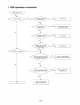
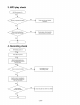
1. USB operation connection USB connection to PC YES NO PC detects USB? NO Set's L463 both terminal voltage is 5V? JK461 check. YES NO C402 one voltage B to B connector connection or PCB Pattern check. terminal is 5V? YES YES C419 +voltage is 3V C422 +voltage is 1.5V? NO IC401 defective. YES Resistance between JK461 #5 and JK461 Frame is less than 10Ω? NO JK461 defective.
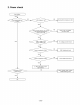
2. Power check Insert battery YES NO When NO L403 pressing play key, EL lisghts? voltage Check is 1.5V? path from battery to L403. YES NO When pressing play key, one of L403 pins does normal switching? (about 3.2V on/off) IC401 or 3V, 1.3V related part short check YES C422 + C419+ YES votage is 1.
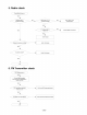
3. MP3 check play MP3 Mode power On YES NO Play key is pressed normally? Check each key and related resistance. YES When pressing play key, sound comes out normally? NO Check volume, then check the path form line out to JK405 YES OK 4. Recording check MP3 Mode power On YES Press REC key twice. YES Stop by pressing play key, playing by pressing play key again. then start YES Voice is recored NO normally? Check MIC401 and surrounding circuit.
5. Radio check Radio Mode Power on YES Channel seek is counted normally? NO NO Seek TU401 6, 7 is counted normally? R449, R448, R414 TU401 check. YES 3V YES NO out form TU401 #4? comes IC402 related circuit check. YES TU401 check Frequency tuning is working? L404, L408 check YES Sound is normal? C438, C439 check. YES OK 6. FM Transmitter check MP3 Mode power on YES Connect FM Transmitter, then turn on FM Transmitter using menu by key.
INTERNAL BLOCK DIAGRAM OF ICs Main CPU STMP 3520 ? BLOCK DIAGRAM Tuner Module MP301 ? Right BLOCK DIAGRAM Out Left Out VDD_FM 4 1,3,5,8 67 I2C Clock I2C Data -2-6-
EL Driver D355B ? Block Diagram -2-7-
MEMO -2-8-
BLOCK DIAGRAM 2-9 2-10
SCHEMATIC DIAGRAM ? MAIN SCHEMATIC DIAGRAM 2-11 2-12
? JACK SCHEMATIC DIAGRAM 2-13 2-14
? MEMORY SCHEMATIC DIAGRAM 2-15 2-16
PRINTED CIRCUIT DIAGRAMS ? MAIN P.C.
? JACK P.C.
? MEMORY P.C.
SECTION 3. EXPLODED VIEWS ? CABINET AND MAIN FRAME SECTION NOTE) Refer to "SECTION 4 REPLACEMENT PARTS LIST" in order to look for the part number of each part.