ENGLISH ITALIANO ESPAÑOL FRANÇAIS INSTALLATION MANUAL AIR CONDITIONER TYPE : CEILING CASSETTE www.lg.com P/NO : MFL42291407 DEUTSCH • Please read this installation manual completely before installing the product. • Installation work must be performed in accordance with the national wiring standards by authorized personnel only. • Please retain this installation manual for future reference after reading it thoroughly.
Multi Type Air Conditioner Installation Manual CONTENTS OUT-LINE OF INSTALLATION Safety Precautions ..........................................................................................3 Installation of Indoor ......................................................................................6 1) Selection of the best location......................6 2) Ceiling opening dimensions and hanging bolt location(unit: mm) ................................8 3) The Indoor Unit Installation....................
Safety Precautions Safety Precautions WARNING This symbol indicates the possibility of death or serious injury. CAUTION This symbol indicates the possibility of injury or damage. ■ Meanings of symbols used in this manual are as shown below. Be sure not to do. Be sure to follow the instruction. WARNING ■ Installation Do not use a defective or underrated circuit breaker. Use this appliance on a dedicated circuit.
Safety Precautions Do not modify or extend the power cable. Be cautious when unpacking and installing the product. • There is risk of fire or electric shock. • Sharp edges could cause injury. Be especially careful of the case edges and the fins on the condenser and evaporator. For installation, always contact the dealer or an Authorized Service Center. Do not install the product on a defective installation stand. • There is risk of fire, electric shock, explosion, or injury.
Safety Precautions CAUTION Always check for gas (refrigerant) leakage after installation or repair of product. Install the drain hose to ensure that water is drained away properly. • Low refrigerant levels may cause failure of product. • A bad connection may cause water leakage. Keep level even when installing the product. Do not install the product where the noise or hot air from the outdoor unit could damage the neighborhoods. • To avoid vibration or water leakage.
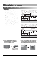
Installation of Indoo Installation of Indoor Selection of the best location Ceiling Board 30 or less 50 or more 50 or more Above 250 330 or less Ceiling Ceiling Board 100 or more Unit:cm Floor Above 250 330 or less 50 or more 100 or more Ceiling Ceiling Board Ceiling Board 50 or more 30 or less 20 or more • There should not be any heat source or steam near the unit. • There should not be any obstacles to prevent the air circulation. • A place where air circulation in the room will be good.
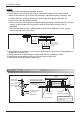
Installation of Indoor Ceiling opening dimensions and hanging bolt location 585~660 585~660 319 570 517 570 517 523 • Select and mark the position for fixing bolts and piping hole. • Decide the position for fixing bolts slightly tilted to the drain direction after considering the direction of drain hose. • Drill the hole for anchor bolt on the wall. Ceiling 461 Unit: mm Level gauge 875 875 840 684 840 CAUTION: • This air-conditioner uses a drain pump.
Installation of Indoor NOTICE • Thoroughly study the following installation locations: 1. In such places as restaurants and kitchens, considerable amount of oil steam and flour adhere to the turbo fan, the fin of the heat exchanger and the drain pump, resulting in heat exchange reduction, spraying, dispersing of water drops, drain pump malfunction, etc.
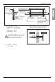
Installation of Indoor Ceiling Spring washer (M10) Flat washer for M10 (accessory) Nut (W3/8 or M10) 90mm Flat washer for M10 (accessory) Ceiling board Air Conditioner body Keep the length of *( )mm between the air conditioner bottom surface and the ceiling surface Paper model for installation Adjust the same height • The following parts is option. ① Hanging Bolt - W 3/8 or M10 ② Nut - W 3/8 or M10 ③ Spring Washer - M10 ④ Plate Washer - M10 CAUTION: Tighten the nut and bolt to prevent unit falling.
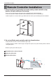
Installation of Indoor Remote Controller Installation 1. Please fix tightly using provided screw after placing remote controller setup board on the place where you like to setup. - Please set it up not to bend because poor setup could take place if setup board bends. Please set up remote controller board fit to the reclamation box if there is a reclamation box. - Install the product so as not to make a gap with the wall side and to prevent shaking after the installation. 2.
Installation of Indoor - Please connect not to make a gap at the remote controller and setup boardʼs upper and lower, right and left part. - Before assembly with the installation board, arrange the Cable not to interfere with circuit parts. When separating remote controller from setup board, as the picture below, after inserting into the lower separating hole using screw driver and then, spinning clockwise, remote controller is separated.
Installation of Indoor Wiring Connection • Open the control box cover and connect the Remote controller cord and Indoor power wires. Connecting Cable Remote Controller Cable L Terminal Block of Indoor Unit 1(L) 2(N) 3 4 Terminal Block of Outdoor Unit N 1(L) 2(N) 3 4 5 TO AIR FRESH KIT POWER INPUT OPTION WARNING: Make sure that the screws of the terminal are free from looseness.
Installation of Indoor ELECTRICAL WIRING Installation Manual 13 ENGLISH 1. All wiring must comply with LOCAL REGULATIONS. 2. Select a power source that is capable of supplying the current required by the air conditioner. 3. Feed the power source to the unit via a distribution switch board designed for this purpose. 4. The terminal screws inside the control box may be loose due to vibration during transport. Check the screws for loose connection.
Installation of Indoor Connecting Pipes to the Indoor Unit Preparation of Piping Main cause of gas leakage is defect in flaring work. Carry out correct flaring work in the following procedure. Copper tube Slanted Uneven Rough 90 1. Cut the pipes and the cable. • Use the accessory piping kit or the pipes purchased locally. • Measure the distance between the indoor and the outdoor unit. • Cut the pipes a little longer than measured distance. • Cut the cable 1.5m longer than the pipe length.
Installation of Indoor Piping Connection 1. Form the piping according to its routing. Avoid bending and bending back the same piping point more than three times. (This will result in hardening the pipe.) 2. After deforming the piping, align centers of the union fitting of the indoor unit and the piping, and tighten them firmly with wrenches. 3. Connect pipe to the service valve or ball valve which is located below the outdoor unit. 4.
Installation of Indoor Installation of Decorative Panel The decorative panel has its installation direction. Before installing the decorative panel, always remove the paper template. 1. Remove the packing and take out air inlet grille from front panel. Front grille 2. Remove the Corner covers of the panel. Coner cover 3. Fit the panel on the unit by inserting hooks as shown in picture. Hook clip Hook 4. Insert two screws on diagonal corners of panel. Do not tighten the bolts completely.
Installation of Indoor 5. Fit the corner covers. ENGLISH 6. Open two screws of control panel cover. Screw 7. Connect one display connector and two vane control connectors of front panel to indoor unit PCB. The position marking on PCB is as: Display connector : CN-DISPLAY Vane control connector: CN-VANE 1,2 CN-VANE 1,2 CN-DISPLAY 8. Close the cover for control box. 9. Install the air inlet grille and Filter on the panel.
Installation of Indoor CAUTION: Install certainly the decorative panel. Cool air leakage causes sweating. ⇨ Water drops fall. Good example Bad example Air conditioner unit Air conditioner unit Air Ceiling board Cool air leakage (no good) Ceiling board Decorative panel Decorative panel Fit the insulator (this part) and be careful for cool air leakage Indoor Unit Drain Piping • Drain piping must have down-slope (1/50 to 1/100): be sure not to provide up-and-down slope to prevent reversal flow.
Installation of Indoor HEAT INSULATION 2. Precautions in high humidity circumstance: This air conditioner has been tested according to the "KS Standard Conditions with Mist" and confirmed that there is not any default. However, if it is operated for a long time in high humid atmosphere (dew point temperature: more than 23°C), water drops are liable to fall.
Test running 2. Connection of power supply 1. Connect the power supply cord to the independent power supply. • Circuit breaker is required. 2. Operate the unit for fifteen minutes or more. 3. Evaluation of the performance 1. Measure the temperature of the intake and discharge air. 2. Ensure the difference between the intake temperature and the discharge one is more than 8°C (Cooling) or reversely (Heating).
Optional Operation Optional Operation ENGLISH Installer Setting -Test Run Mode After installing the product, you must run a Test Run mode. For details related to this operation, refer to the product manual. pressing button long for 3 seconds, 1 Ifit enters into remote controller setter setup mode. - If pressing once shortly, it enters into user setup mode. Please press more than 3 seconds for sure. - Please cancel the right and left of wind direction for RAC product.
Optional Operation Installer Setting - Setting Address of Central Control It's the function to use for connecting central control. Please refer to central controller manual for the details pressing button long for 3 1 Ifseconds, it enters into remote controller setter setup mode. - If pressing once shortly, it enters into user setup mode. Please press more than 3 seconds for sure. into address setup mode by using 2 If entering button, it indicates as picture below. Indoor No.
Optional Operation Installer Setting -Thermistor This is the function to select the temperature sensor to judge the room temperature. controller setter setup mode. - If pressing once shortly, it enters into user setup mode. Please press more than 3 seconds for sure. 2 If moving to room temperature perception sensor selection menu by pressing button, it indicates as picture below. Thermistor value by pressing 3 Set button.
Optional Operation Installer Setting -Ceiling Height Selection This function is to adjust FAN Airflow rate according to ceilingheight (only cassette model) pressing button long for 3 1 Ifseconds, it enters into remote controller setter setup mode. - If pressing once shortly, it enters into user setup mode. Please press more than 3 seconds for sure. 2 If moving to ceiling height selection menu by pressing button, it indicates as picture below. height value by pressing 3 Select ceiling button.
Optional Operation Installer Setting-Group Setting It is a function for settings in group control, or 2-remote controller control. controller setter setup mode. - If pressing once shortly, it enters into user setup mode. Please press more than 3 seconds for sure. 2 If pressing button repeatedly, it moves to master/slave selection menu as picture below. Master/ Slave by pressing 3 Select button. (00: Slave, 01: Master) Function Code 4 Press Master/Slave value button to save.
Optional Operation Installer Setting-Dry Contact Mode Setting Dry contact function is the function that is possible to use only when dry contact equipment is separately purchased/setup. pressing button long for 3 1 Ifseconds, it enters into remote controller setter setup mode. - If pressing once shortly, it enters into user setup mode. Please press more than 3 seconds for sure. pressing button repeatedly, it moves to 2 Ifremote controller dry contact mode setup menu as picture below.
Optional Operation Installer Setting-Celsius / Fahrenheit Switching pressing button long for 3 1 Ifseconds, it enters into remote controller setter setup mode. - If pressing once shortly, it enters into user setup mode. Please press more than 3 seconds for sure. pressing 2 Repeat Function code 12. button to select Function Code conversion mode value Ex) Fahrengeit Setting Temperature unit mode by 3 Select pressing button. (00: Celsius, 01: Fahrenheit) 4 Press button to save or release.
Optional Operation Installer Setting -Optional Function Setting Setting feature for indoor unit when air cleaning / heater / humidifier / Up/down grill / Ventilation KIT /Auxiliary Heater is newly installed, or installed unit is removed. pressing button long for 3 1 Ifseconds, it enters into remote controller setter setup mode. - If pressing once shortly, it enters into user setup mode. Please press more than 3 seconds for sure.