
Installation guide
35
ENGLISH
CAUTION
!
It should be wiring power cables or communication cables to
avoid interference with the oil level sensor. Otherwise, That oil
level sensor would be operated abnormally.
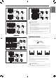
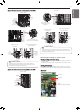
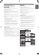
Example) Connection of power and communication cable (UXA)
Gap : Over
50 mm(1.97’’)
When connecting
Main power lines
/ Ground wire from left side
When connecting
Communication wires
/ Ground wire from left side
Main power
terminal block
Ground wire
Main power
terminal block
Insulation sleeves
attachments
Ground wire
Ground wire
ODU-IDU
Communication
cable
ODU-ODU
Communication
cable
Bottom Side
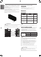
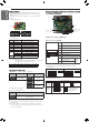
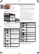
Main power
terminal block
Ground wire
When connecting
Communication wires
/ Ground wire from
front guide panel
When connecting
Main power lines
/ Ground wire from
front guide panel
Gap : Over
50 mm(1.97’’)
Front Side
Fix firmly with cable tie or
clamp cord not to be displaced
Main power line
connection
Communication/Ground
wire connection
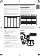
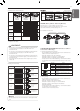
Example) Connection of power and communication cable (UXB)
Main power
terminal block
Ground wire
Gap : Over
50 mm(1.97’’)
When connecting
Main power lines
/ Ground wire from left side
When connecting
Communication wires
/ Ground wire from left side
Bottom Side
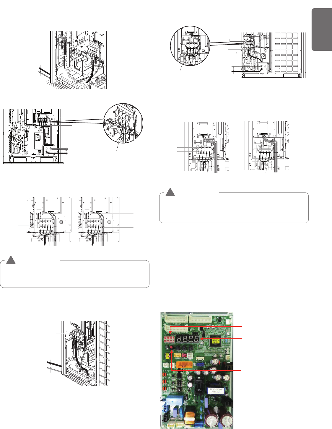
CAUTION
!
It should be wiring power cables or communication cables to avoid
interference with the oil level sensor. Otherwise, That oil level sensor
would be operated abnormally.
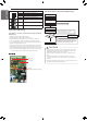
DIP switch
7 segment
SW01C
(Automatic Addressing Setting)
Main power
terminal block
Insulation sleeves
attachments
Ground wire
Ground wire
ODU-IDU
Communication
cable
ODU-ODU
Communication
cable
Main power
terminal block
Ground wire
When connecting
Communication wires
/ Ground wire from
front guide panel
When connecting
Main power lines
/ Ground wire from
front guide panel
Gap : Over
50 mm(1.97’’)
Front Side
Fix firmly with cable tie
or clamp cord not to be
displaced
Main power line
connection
Communication/Ground
wire connection
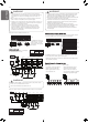
Checking the setting of outdoor units
Checking according to DIP switch setting
- You can check the setting values of the Master outdoor unit from the
7 segment LED.
The DIP switch setting should be changed when the power is OFF.
Checking the initial display
The number is sequentially appeared at the 7 segment in 5 seconds
after applying the power. This number represents the setting condition.
[Main Board]