
Installation guide

37
ENGLISH
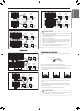
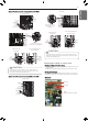
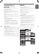
3 Selection of the model of HR unit
* Each model is shipped with the switches No.2 and No.3 pre-adjusted
as above in the factory.
(For 2 branches)
PRHR022
PRHR022A
(For 3 branches)
PRHR032
PRHR032A
(For 4 branches)
PRHR042
PRHR042A
Initial
Setting
1 branches
Connected
2 branches
Connected
3 branches
Connected
4 branches
Connected
1
2
3
1
2
1
3
2
4
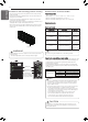
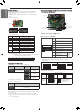
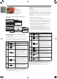
4 Setting the Valve Group.
WARNING
!
• If you want to use a PRHR032 or PRHR032A for 2 branches HR
unit after closing the 3rd pipes, set the DIP switch for 2
branches HR unit.
• If you want to use a PRHR042 or PRHR042A for 3 branches HR
unit after closing the 4th pipes, set the DIP switch for 3
branches HR unit.
• If you want to use a PRHR042 or PRHR042A for 2 branches HR
unit after closing the 3rd and 4th pipes, set the DIP switch for 2
branches HR unit.
• The unused port must be closed with a copper cap, not with a
plastic cap.
No.1, 2 Valve
/
No.3, 4 Valve
Control
No.3, 4 Valve
Control
DIP S/W setting
No.2, 3 Valve
Control
No.1, 2 Valve
Control
Not control
Example
Large capacity indoor unit
Large capacity indoor unit
1
2
3
4
Indoor Unit
Indoor Unit
Large capacity indoor unit
1
2
3
4
Indoor Unit
Indoor Unit
Large capacity indoor unit
1
2
3
4
Indoor Unit
Indoor Unit
Large capacity indoor unit
1
2
3
4
Indoor Unit
Indoor Unit
Indoor Unit
Indoor Unit
1
2
3
4
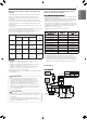
I.D 6.35(1/4)
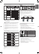
NOTE
!
If the large capacity indoor units are installed, below Y branch pipe should be
used.
Models Low pressure Gas pipe High pressure Gas pipeLiquid pipe
ARBLB03321
413(16-1/4)
390(15-11/32)
I.D 19.05(3/4)
I.D 19.05(3/4)
I.D 19.05(3/4)
I.D 15.88(5/8)
I.D 12.7(1/2)
I.D 12.7(1/2)
I.D 12.7(1/2)
I.D 12.7(1/2)
I.D 12.7(1/2)
I.D 12.7(1/2)
I.D 12.7
(1/2)
74
(2-29/32)
70(2-3/4)
70(2-3/4)
I.D 15.88(5/8)
I.D 15.88(5/8)
I.D 25.4(1)
I.D 25.4(1)
I.D 25.4(1)
O.D 25.4(1)
80(3-5/32)
110(4-11/32) 110(4-11/32)
332(13-1/16)
321(12-5/8)
83
(3-9/32)
1
2
3
3
I.D 19.05(3/4)
I.D 19.05(3/4)
O.D 19.05(3/4)
O.D 19.05(3/4)
2
3 2
3
1 2
O.D 15.88(5/8)
444(17-15/32)
421(16-9/16)
96
(3-25/32)
I.D 15.88
(5/8)
I.D 22.2(7/8)
I.D 22.2(7/8)
I.D 22.2(7/8)
I.D 22.2(7/8)
I.D 22.2(7/8)
I.D 22.2(7/8)
O.D 15.88(5/8)
I.D 6.35(1/4)
I.D 28.58(1-1/8)
I.D 19.05(3/4)
I.D 9.52(3/8)
I.D 9.52(3/8)
I.D 9.52(3/8)
I.D 9.52(3/8)
I.D 6.35(1/4)I.D 6.35(1/4)I.D 6.35(1/4)
Y branch pipe
(Unit: mm [inch])
1
2
3
4
1
2
3
4
1
2
3
4
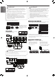
AB AB AB
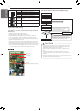
S/W No. Setup
No.1 Manual addressing of valve #1
No.2 Manual addressing of valve #2
No.3 Manual addressing of valve #3
No.4 Manual addressing of valve #4
SW03M
Increase in the digit of 10 of valve
address
SW04M
Increase in the last digit of valve
address
SW01M
SW03M
SW04M
2 Zoning setting
- Set the address of the valve of the HR unit to the central control
address of the connected indoor unit.
- SW01M : selection of the valve to address
SW03M : increase in the digit of 10 of valve address
SW04M : increase in the last digit of valve address
SW05M :Rotary S/W
- Prerequisite for manual valve addressing : central control address
of each indoor unit must be preset
differently at its wired remote control.
SW01M/SW03M/SW04M (DIP S/W and tact S/W for
manual valve addressing)
1 Normal setting (Non-Zoning setting)
- Set the address of the valve of the HR unit to the central control
address of the connected indoor unit.
- SW01M: selection of the valve to address
SW03M: increase in the digit of 10 of valve address
SW04M: increase in the last digit of valve address
- Prerequisite for manual valve addressing : central control address
of each indoor unit must be preset differently at its wired remote
control.
SW05M (Rotary S/W for addressing HR unit)
Must be set to '0' when installing only one HR unit.
When installing multiple HR units, address the HR units with
sequentially increasing numbers starting from '0'.
Ex) Installation of 3 HR units