
Installation guide

40
ENGLISH
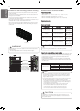
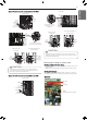
SW01C (Ɨ: Confirm /
Automatic Addressing)
SW02C (ȭ: backward)
SW04C (X : cancel)
DIP-SW01
7-Segment
SW01D (reset)
SW03C (ȯ: forward)
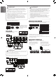
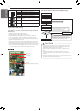
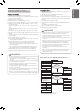
Completion of manual pipe detection
process
Reset the power of HR unit PCB.
Input the central control address at each
indoor unit using wired remote controller.
Set the address of each valve manually
by referring indoor unit’s central control
address connected with.
Reset the power of outdoor unit PCB.
Wait for about 5 minutes.
The number of the indoor units connected
is displayed.
Ex) HR रThe number of connected
indoor units
Check the central control address of
indoor and HR unit.
Make sure that reset the outdoor
Unit’s power after setting central
control address of indoor unit’s
Is the number
of indoor units connected with the
outdoor unit and displayed
number equal?
Execute in case of Auto pipe detection
failure
Turn No.1 of SW02M of HR unit PCB on.
NO
YES
- Above setup must be done for all HR unit valves.
- The valve that is not connected with any indoor unit should be
addressed with any other number than used address numbers of the
valves connected with indoor units.
(The valves does not work if the address numbers are same.)
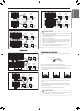
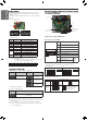
No. Display and setup Setup and Contents
1
- Operation: None
- Display: None
2
- Operation: Turn DIP S/W No.1 on to
address valve #1
- Display: Existing value saved in
EEPROM is displayed in 7-SEG.
3
- Operation: Set the digit of 10 to the
number in Group High data of the wired
remote control connected to the
corresponding indoor unit to the valve
#1 by pressing left tack S/W.
- Display: Digit increasing with the times
of pressing tack S/W is displayed in left
7-SEG
4
- Operation: Set the digit of 1 to the
number in Group Low data of the wired
remote control connected to the
corresponding indoor unit to the valve
#1 by pressing right tack S/W.
- Display: Digit increasing with the times
of pressing tack S/W is displayed in
right 7-SEG
5
- Operation: Turn DIP S/W No.1 off to
save the address of valve #1
- Display: "11" displayed in 7-SEG
disappears
7-SEG SW01M SW03M SW04M
7-SEG SW01M SW03M SW04M
7-SEG SW01M SW03M SW04M
7-SEG SW01M SW03M SW04M
7-SEG SW01M SW03M SW04M
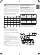
- Above setup must be done for all HR unit valves.
- The valve that is not connected with any indoor unit should be
addressed with any other number than used address numbers of the
valves connected with indoor units.
(The valves does not work if the address numbers are same.)
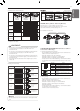
No. Display and setup Setup and Contents
1
- Operation: None
- Display: None
2
- Operation : Turn DIP S/W No.1 on to
address valve #1
- Display : Existing value saved in
EEPROM is displayed in 7-SEG.
3
- Operation : Set the digit of 10(1) to the
number in Group High data of the wired
remote control connected to the
corresponding indoor unit to the valve
#1 by pressing left tack S/W.
- Display : Digit increasing with the times
of pressing tack S/W is displayed in left
7-SEG.
4
- Operation : SW05M : 1
- Display : Display former value.
5
- Operation : Setting No. using SW03M
and SW04M, SW05M : 1
- Display : Display setting value.
6
- Operation : Turn DIP S/W No.1 off to
save the address of valve #1
- Display : "11" displayed in 7-SEG
disappears.
7
- Operation : Return valve of addressing
HR unit.
- Display : None
7-SEG SW01M SW03M SW04M
0
SW05M
7-SEG SW01M SW03M SW04M
SW05M
0
7-SEG SW01M SW03M SW04M
SW05M
0
1
7-SEG SW01M SW03M SW04M
SW05M
7-SEG SW01M SW03M SW04M
SW05M
1
7-SEG SW01M SW03M SW04M
SW05M
1
7-SEG SW01M SW03M SW04M
SW05M
0
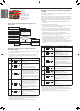
Example of manual valve addressing (Zoning
setting)
(In case that an indoor unit of central control address "11" is connected
to a valve #1 of an HR unit)
Zoning control is connecting 2 or more indoor units at one pipe of HR
unit. In case of Zoning control, in order to set controls with multiple
indoor units connection uses the rotary switch. Namely, only the rotary
switch changes from same valve set condition and set indoor units
connection.
1 On DIP switch of the corresponding valves and sets the rotary
switch at 0.
2 Setting the number with tact switch.
3 In case of addition of indoor units to same port, increases 1 with the
rotary switch and sets number with tact switch.
4 In case of checking the number which the corresponding valve is
stored, turn on DIP switch and set the number of rotary switch.
5 Indoor units set available 7 per a port(rotary switch 0~6), in case of
setting above of 7 with rotary switch, it will display error.
6 Setting the rotary switch on original condition(HR unit number set
conditions) after all finishing a piping setting.
7 The rotary switch set value of above number of indoor units which
is connected with FF and prevents a malfunction.
(Example: The case where 3 indoor units is connected in piping 1,
sets from rotary switch 0, 1, 2 and 3, 4, 5 with FF set)
- Prerequisite for manual valve addressing: central control address of
each indoor unit must be preset differently at its wired remote
control.
Example of manual valve addressing (Non-
Zoning setting)
(In case that an indoor unit of central control address "11" is connected
to a valve #1 of an HR unit)
- Prerequisite for manual valve addressing: central control address of
each indoor unit must be preset differently at its wired remote
control.
Flow chart of manual addressing for pipe
detection