Installation Instructions BRENTWOOD This installation manual will help you obtain a safe, efficient, dependable installation for your fireplace and chimney system. Please read and understand these installation instructions before beginning your installation. CAUTION: Do not attempt to modify or alter the construction of the fireplace or its components. Any modification or alteration of construction may void the warranty, listings and approvals of this system.
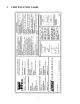
TABLE OF CONTENTS Page 1. SAFETY RULES ................................................................................................. 1 2. CERTIFICATION LABEL ................................................................................ 2 3. THE FIREPLACE ............................................................................................... 3 4. 3.1 INTRODUCTION .................................................................................................................. 3 3.1.
1. SAFETY RULES FOR OPERATING YOUR FIREPLACE MODEL BRENTWOOD • Use only a Lennox Hearth Products glass door, specifically designed for the model BRENTWOOD fireplace. • When cleaning the fireplace, the ashes should be placed in a metal container with a tight fitting lid. The closed container of ashes should be placed on a non-combustible floor or on the ground outside the house, pending final disposal.
2.
3. THE FIREPLACE 3.1 INTRODUCTION The BRENTWOOD fireplace is an energy efficient, heat circulating, close combustion fireplace. You will receive a lifetime of comfort and enjoyment from your fireplace provided it is installed, maintained and operated properly. • Please read these instructions and retain this manual for future reference. • Before beginning the fireplace installation, consult the local authorities to obtain your building permit and check your local building codes.
3.2 OPERATING THE BRENTWOOD 3.2.1 Fuel The BRENTWOOD is designed to work best when fuelled with seasoned cordwood. Hardwoods are preferred to softwoods since the energy content of wood is relative to its density. Hardwoods will result in a longer burning fire and less frequent refuelling. A moisture content of 15% to 20% (seasoned) is recommended. Wood that has been cut and split and let to dry under a cover for a period of one year will usually meet that criteria.
3.2.4 Primary Air and Air Boost Controls There is no flue damper in the BRENTWOOD. As is common with air tight stoves, the combustion air control sets the flow of air entering the firebox. This allows for a more precise control of the fire. The combustion air control is located below the door on the left side. The main source of air (primary air) entering the firebox can be diminished by moving the air combustion control from left to right.
3.2.6 Medium Combustion This is the recommended mode of operating the BRENTWOOD and should be the one normally used since it will deposit the least amount of creosote on the glass and in the chimney. The combustion air control must be 3/4 closed and pushed forward to close the air boost. The precise setting will depend on many factors, including chimney length and the moisture content of the wood. For instance, a long chimney will necessitate closing the damper more.
3.2.9 Smoking – Causes and Troubleshooting To reduce the likelihood of smoking when opening the door, set the combustion air controls to the left before opening the door. Your fireplace has been designed and tested to provide smoke free operation. Occasionally, there may be a small amount of smoking upon lighting the fire, until the chimney heats up but this should not continue. If the fireplace continues to smoke it is probably for one of the following reasons: A.
IMPORTANT NOTES A. Do not block the hot air vents to the fireplace as this will cause the fireplace to overheat. B. Never start a fire using gasoline, kerosene, charcoal lighter fluid or any other combustible liquid. C. Do not burn coal. The sulphur in coal will corrode the firebox. D. Do not burn driftwood which has been in the ocean or salt water. The salt will corrode the firebox and chimney. E. Do not burn wood in the area in front of the grate. F.
3.3.3 Top Baffle Removal Prior to Cleaning The Chimney Before starting to clean your chimney, we recommend that you remove the top baffle to avoid creosote dust collection at the top of the baffle. Follow these steps to set the top baffle out of the way: 1. Remove the side refractory holder. They are located at the top of the refractory. 2. Lift the front baffle. 3. Slide the back baffle under the front baffle. You now have access to the chimney. 3.3.
3.3.7 Refractory Replacement The intense heat of the fire will normally cause hairline cracks in the refractory. These cracks can be minimized by proper curing as described in "First Fires". They will not normally diminish the effectiveness of the refractory. If large cracks develop, then the refractory should be replaced. To replace the refractory bricks, follow these steps: 1. 2. 3. 4. 5. 6. 7.
3.3.9 Door Adjustment The door may need to be adjusted to be completely airtight. The gaskets’ air-tightness can be adjusted using the adjustment screw located on the right side of the fireplace façade. (An Allen key #1/8 – not supplied - will be necessary for this adjustment) Figure 4 3.3.10 Glass Care - Replacement The glass used for the BRENTWOOD is a high temperature ceramic glass (1400° F). If the glass breaks, it must be replaced with an identical ceramic glass.
3.4 FIREPLACE INSTALLATION 3.4.1 Locating The BRENTWOOD A. The best location to install your fireplace is determined by considering the location of windows, doors, and the traffic flow in the room where the fireplace is located, allowing space in front of the unit for the hearth extension and the mantel, and taking into consideration the location of the hot air ducts (optional), outside air kit and chimney.
3.4.3 Framing, Facing And Mantel The construction of the framing, facing, and mantel must be in accordance with the standards and the following illustrations (figures 6 to 10): A. Frame the fireplace using 2" x 3" or heavier lumber. B. WARNING: Combustible materials cannot be used in the space directly above the fireplace, except for the studs above the facade that support the facing and mantel. This area must remain empty for a height of 6'8" (2032 mm) measured from the base of the appliance. C.
INSULATED CHASE CONSTRUCTION Figure 10 14
Facing 1. Combustible material must be installed flush with the fireplace. It may not project in front of and on the fireplace (i.e. the steel façade of the fireplace) (figure 11). 2. Non-combustible materials such as brick, stone or ceramic tile may project in front of and onto the fireplace facing (figure 12). Mantel The mantel must be installed at least 45" (1143 mm) above the base of the fireplace (figure 11).
3.5 - HOT AIR DUCTING INSTALLATION Different hot air ducting systems can be installed with the BRENTWOOD: - Gravity kit Forced air kit 3.5.1 Gravity Kit Two kits are available: 1. Single hot air outlet including: (see Fig.13) - 2 6" lengths 8" I.D. - 1 hot air outlet kit (box, louver and frame) - 2 adaptors 2. Double hot air outlet including: (See Fig.14) - 2 telescopic lengths 8" I.D. - 2 90º elbows 8" I.D.
The single outlet system is designed to be installed either flush with the front of the BRENTWOOD or extended out slightly from the face of the fireplace (if installing with a brick or thick facing for example). To extend the double outlet system, it will be necessary to purchase two adjustable lengths (7B26ZL2A). To extend the single outlet, it is necessary to install the insulation strip provided with the system.
The duct system must be installed respecting the following: 1. Remove the plates closing up the 8" dia. holes on top of the fireplace. Then, cut the insulation in order to obtain two 8" dia. openings. Fix the adaptors on the fireplace openings by turning clockwise (figures 13 and 14). 2. Maintain at least a 2" (50 mm) clearance between the ducts and any combustible material; the required hole size is 13" x 13" (330 mm x 330 mm).
3.6 OUTSIDE AIR KIT (Optional) During operation, the fireplace requires fresh air for combustion and draws air out of the house. It may starve other fuel burning appliances such as gas or oil furnaces. As well, exhaust fans may compete for air, causing negative pressure in the house, resulting in smoke entering the house from the fireplace. This situation is aggravated in modern airtight houses. To overcome this problem, we strongly recommend that you install an outside air assembly.
3.6.2 AC CHIMNEY OUTSIDE AIR KIT (Optional) * The outside air assembly for the AC (Air Cool) chimney is mandatory in some areas. Check with your local building authority for the requirements in your area. All required parts for outside air assembly are contained in the following kit: ACZIB 1) Install the outside air kit box and collar on the top of the unit. Install the flex 4" adaptor on the top of the outside air kit box. 2) Install the outside air register as described in the preceding section (3.6.1).
4. THE CHIMNEY 4.1 CHIMNEY INSTALLATION NOTES 1. Always install an interior chimney as it will provide better performance. In areas with continuous temperatures below -18° C (0° F), the use of an exterior chimney increases the likelihood of operating problems such as low draught, high rate of creosoting, and poor start-up characteristics. Exterior chimneys are also prone to down drafting and flow reversal.
4.2 CHIMNEY INSTALLATION INSTRUCTIONS 1. Cut and frame the holes in the ceiling, floor and roof where the chimney will pass (see figure 22). Use a plumb bob to line up the center of the holes. The sizes are indicated in table 1 for the floor and ceiling holes and table 2 (page 24) for the roof holes. CHIMNEY MODEL SQUARE HOLE SIZE OPENING AC 15 in. Table 1 Figure 22 2. From below, install a firestop in each ceiling/floor separation through which the chimney will pass.
AC CHIMNEY INSTALLATION (AIR COOLED GALVALUME CHIMNEY) Figure 24 23
AC CHIMNEY Figure 25 Figure 26 Table 2 ROOF DOWN SLOPE HOLE SIZE SLOPE Roof Pitch AC 6" 15" (380 mm) 0* 2/12 15 3/8" (390 mm) 4/12 16 1/8" (410 mm) 6/12 16 7/8" (430 mm) 8/12 18 1/4" (465 mm) 10/12 19 5/8" (500 mm) 12/12 21 3/8" (545 mm) * CROSS SLOPE HOLE SIZE 24
4.3 OFFSET CHIMNEY INSTALLATON The minimum chimney height when using elbows is: Fireplace model Chimney model Vertical installation Two (2) elbows Four (4) elbows BRENTWOOD AC 12 ft. (3.66 m) 15 ft. (4.57 m) 17 ft. (5.18 m) Table 3 After reaching the location requiring the elbow, proceed as follows: AC Chimney 1. Install the first elbow. Turn it in the required direction. To lock it in place, turn 1/8 of a turn.
Table 4 26
4.4 ANGLED WALL RADIATION SHIELD (ACRSM30, ACRSMI30) When traversing a combustible wall with the chimney at a 30º, an angled firestop or wall radiation shield must be installed. Only one is required. In cold climate locations, we recommend that you use the insulated wall radiation shield since it will maintain the home’s thermal barrier. RSM+ and RSMI30, RSMI45 CHIMNEY MODEL AC (6" dia.
4.5 CHIMNEY SUPPORT INSTALLATION Universal Roof Support This support has two possible uses: 1. It may be used on a floor, ceiling or roof above an offset to support the chimney above the offset. 2. It may be used on a floor, ceiling or roof as a supplementary support Table 6 gives maximum height of supported chimney. NOTE: For the AC chimney, a support section may be used every 40 ft. (12 m) instead of the universal roof support (ST).
Figure 29 29
5. PARTS AND COMPONENTS LIST (AC Chimney) Description Part No. Lengths 6" dia.
6. OPTIONS Gravity kit: Part No.: Catalog No. Complete double ducting system including: 2 elbows 90º, 2 telescopic lengths, 2 grill supports and 2 black grills Complete single ducting system including: 2 x 6" lengths, 1 decorative black frame and 1 black louver Complete single ducting system including: 2 x 6" lengths, 1 decorative brass frame and 1 brass louver Black grill with support Brass grill for 7B30ZK 1 brass louver & 1 decorative brass frame Elbow 90º, 8" dia. Elbow 45º, 8" dia.
7. APPENDIX SPECIFICATIONS Weight Height Width Depth Chimney weight AC (6" dia.) 385 lbs 36" 36" 24 1/2" 3.25 lb/ft. CLEARANCE TO COMBUSTIBLES The following clearances meet the minimum requirements for a safe installation Side wall: 17" (324 mm) measured from the fireplace side Ceiling: 6’ 8" (2032 mm) measured from the base of the fireplace Fireplace enclosure: Bottom: 0” Side: 0” Back: 0” Top: Do not fill the space above the fireplace with any material (Except the wood framing.