
PDRYCB300 Installation Manual


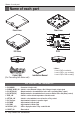

Name of each part
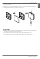
6 Dry contact for thermostat
Name of each part
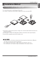
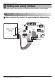
1. CN_INDOOR : Connector for indoor unit
2. CHANGE_OVER_SW : Switch to select External Voltage or Non Voltage for input contact signal
3. CN_OUT(O1,O2) : Output terminal to show whether the indoor unit is operating (Relay contact)
4. CN_OUT(E3,E4) : Output terminal to show whether there is an error with the indoor unit (Relay contact)
5. TEMP_SW : Switch to set the desired temperature of the indoor unit
6. SETTING_SW : Switch to select whether to use set function of Dry contact
7. CN_Ther/oper : Input terminal for thermo & operation signal
8. CN_MODE : Input terminal for Mode signal
9. CN_WIND : Input terminal for Wind signal
10. DISPLAY_LED : LED to display the status of Dry contact Module
11. RESET_SW : Reset switch
DRY CONTACT FOR THERMOSTAT
8
9
10
6
5
3
4
1
7
2
11
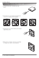
PCB
Front Case Rear Case
ISO View
Side
Cable(1 EA)
(For Connecting with indoor unit)
Installation Manual
Side
* Others :
Screw 4 EA(For installation)
Screw 2 EA(For case assembly)
Screw 2 EA(For PCB assembly)