
Install Instructions


Installation manual 9
Name of each part
8 Modbus Gateway For Indoor Unit
ENGLISH
Specification
Modbus Gateway For Indoor Unit
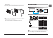
Name of each part
PCB
Front Case Rear Case
ISO View
Side Side
12
ON
34
1
2
3
4
765
8
Cable(1 EA)
(For Connecting with indoor unit)
Connector (1 EA)
(For expanding address range)
Installation Manual
* Others :
Screw 4 EA(For installation)
1. CN-OUT :
2. BUS-A :
3. BUS-B :
4. SW1 :
5. SWDIP :
6. LED1 :
7. LED(01~03)G :
8. CN-JIG :
Indoor Unit Connector
RS-485(+) Terminal
RS-485(-) Terminal
Reset Switch
Setting Address Switch(Refer Page 11)
RS-485 Status LED
Communication Status LED
Connector for expanding the address range
Specification
1) Modbus configuration
- Network : 2 wire RS485
- Mode : Modbus RTU slave
- Baud : 9600
- Parity : None
- Stop bits : 1
- Register Base : 0
2) Data registers
※ Above function may not work in some products.
Function code Register Address Name Range Notes
01(read)/05(write) 00001 0x0000 Operation 0~1
0: Stop
1: Run
04(read) 30001 0x0000 Pipe in temprature -300~1120 Degrees (℃) × 10
04(read) 30002 0x0001 Pipe out temperature -300~1120 Degrees (℃) × 10
04(read) 30003 0x0002 Indoor temperature 100~400 Degrees (℃) × 10
04(read) 30100 0x0063 Error code 0~999
0: No error
1~999: Error code
03(read)/06(write) 40001 0x0000 Set run mode (aircon) 0~4
0: Cool
2: Fan
3: Auto
4: Heat
03(read)/06(write) 40002 0x0001 Set temperature 180~300 Degrees (℃) × 10
03(read)/06(write) 40003 0x0002
Set run mode
(ventilation)
0~2
0: Heat exchange
1: Auto
2: Bypass
03(read)/06(write) 40004 0x0003
Set sub operation
(ventilation)
0~2
0: Off
1: Fast
2: Energy saving
03(read)/06(write) 40015 0x000E Set fan speed 1~3
1: Low
2: Middle
3: High
4: Auto
7: Super High