
Install Instructions


Setting method
Installation manual 13
Installation Method
12 Modbus Gateway For Indoor Unit
ENGLISH
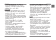
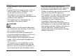
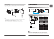
2. Setting Address
After change any Dry contact setting, then you must press RESET switch to reflect the setting.
Indoor unit PCBA
CN_CC
12
ON
34
Modbus
Controller
12
ON
34 12
ON
34
12
ON
34 12
ON
34
12
ON
34 12
ON
34
*Status of switch
- Not attached(default): 1~8
- Attached(expanding address range): 9~16
* /Number: Address when connector is attached
12
ON
34 12
ON
34
Address 1/9 Address 2/10
Address 3/11 Address 4/12
Address 5/13 Address 6/14
Address 7/15 Address 8/16
ON
OFF
12
ON
34
After change any Dry contact setting, then you must press RESET switch to reflect the setting.
h In case, connect a Modbus controller with several product, Address have to be set different from
others.
h If the connector is attached to ‘CN-JIG’, the address range is expanded. (Please attach the
connector before turning on the product.)
5) Connect the connection wires properly according to the connection method. (Refer to the instruction
and set-up description)
6) Set the switch according to the setting method. (Refer to the instruction and set-up description)
7) Tighten the fixing screws on the top and bottom of the case.
*Note
1. Install the product on flat surface and install anchoring screws at more than 2 places. Otherwise
the central controller may not be anchored properly.
2. Do not tighten anchoring screws too tightly. It may cause deformation of the case.
3. Do not deform the case at random. It may cause malfunction of the central controller.
1. Connecting Drycontact with Indoor unit PCBA and Modbus Controller
Setting method